Eureka AIR delivers breakthrough ideas for toughest innovation challenges, trusted by R&D personnel around the world.

Simple method for transforming integrated distribution box into fiber distribution box

A technology of fiber distribution box and distribution box, which is applied in fiber mechanical structure, light guide, optics, etc., can solve the problems of not meeting the actual needs of the market, increasing the operator's input cost, etc., and achieve space saving, energy saving, and simple operation. Effect

Inactive Publication Date: 2018-03-30
JIANGSU TONGDING BROADBAND
View PDF2 Cites 0 Cited by
  • Summary
  • Abstract
  • Description
  • Claims
  • Application Information

AI Technical Summary

Problems solved by technology

However, after the integrated distribution boxes are arranged in many communities, due to space constraints, such as areas such as power drop rooms and shafts, there is no extra space to arrange fiber optic cable distribution boxes again.
If the integrated distribution box is directly removed and the fiber distribution box is reinstalled, it is necessary to upgrade the products of all users and increase the one-time investment cost of the operator, which obviously does not meet the actual needs of the market

Method used


Image

  • Simple method for transforming integrated distribution box into fiber distribution box
  • Simple method for transforming integrated distribution box into fiber distribution box

Examples


Embodiment 1

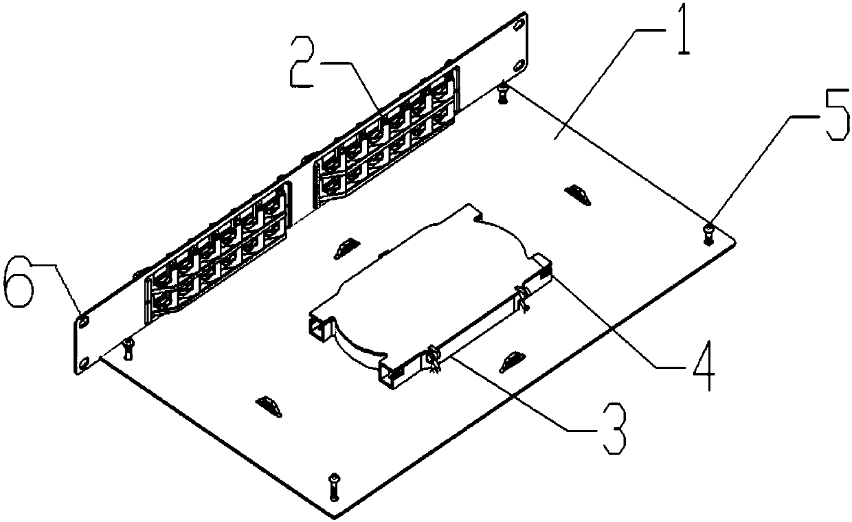
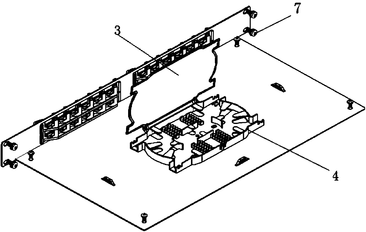
[0019] The fiber distribution box transformation assembly includes a multifunctional installation plate 1, an adapter seat plate 2 and a fiber splice tray assembly 4, the multifunctional installation plate 1 includes a bottom plate and a side plate perpendicular to the bottom plate on the side of the bottom plate, the The size of the multifunctional mounting plate 1 is suitable for a 19-inch wiring box, the height is 1U, and the side plate has a 19-inch mounting hole 6; the splice tray assembly 4 also includes a 24-core splice tray cover 3, so The splice tray assembly 4 is installed in the middle of the base plate through two self-tapping screws through the two mounting holes at the bottom and the two corresponding mounting holes on the base plate, and the adapter seat plate 2 is clamped and mounted on the base plate into the mounting slot on the side panel.

[0020] According to the embodiment of the present invention, a simple method for transforming part of the integrated d...

Embodiment 2

[0022] The fiber distribution box transformation assembly includes a multifunctional installation plate 1, an adapter seat plate 2 and a fiber splice tray assembly 4, the multifunctional installation plate 1 includes a bottom plate and a side plate perpendicular to the bottom plate on the side of the bottom plate, the The size of the multifunctional mounting plate 1 is suitable for a 19-inch wiring box, the height is 1U, and the side plate has a 19-inch mounting hole 6; the splice tray assembly 4 also includes a 24-core splice tray cover 3, so The splice tray assembly 4 is installed in the middle of the base plate by two dovetail groove self-tapping screws through the two mounting holes at the bottom and the two corresponding mounting holes on the base plate, and the adapter seat plate 2 is clamped and mounted on the in the mounting groove of the side panel.

[0023] According to the embodiment of the present invention, a simple method for transforming the integrated distribut...


PUM


Abstract

The invention provides a simple method for transforming an integrated distribution box into a fiber distribution box. The simple method comprises the following steps that firstly the main equipment onthe upper layer of the original integrated distribution box is disassembled and then a fiber distribution box transformation component penetrates through a 19-inch installing hole to be fixed on a 19-inch support through mechanical screws, or the fiber distribution box transformation component is directly fixed on the baseplate of the original box body through self-tapping screws. The advantagesof the simple method are that 1) the integrated distribution box is transformed into the fiber distribution box step by step so as to realize optical fiber accessing; 2) the old box body can simultaneously realize the mode of optical fiber accessing and copper cable accessing after transformation; 3) the fiber distribution box body does not need to be installed again so that the effects of savingenergy and saving space can be realized; and 4) operation is easy and convenient with no requirement for special tools.

Description

technical field [0001] The invention relates to the technical field of optical cable access to the home, in particular to a simple method for transforming an integrated distribution box into a fiber distribution box. Background technique [0002] In the case of FTTB as the mainstream access method, integrated distribution boxes for broadband access are popular, and various operators have carried out rapid deployment. As a result, communication operators have arranged integrated distribution boxes in the corridors or walls of each residential building. , The wiring box is usually installed in 2U 19 inches, and the ONU equipment is 1U high. Each ONU equipment can usually connect 24 users, and the user terminals are all connected by copper cables. [0003] With the development of the network and the continuous advancement of FTTH, broadband access has gradually changed from copper cable access to optical fiber access, and the product has also changed from integrated distributio...

Claims


Application Information

Patent Timeline
IPC IPC(8): G02B6/44
CPCG02B6/4446G02B6/4431
Inventor 刘东洋张红花吴俊生贺方东邓晓燕
Owner JIANGSU TONGDING BROADBAND
Why Eureka
Eureka Blog
Learn More