
Laser safety control method and device based on rang sensor

A distance sensor and safety control technology, applied in the field of optics and electronics, can solve problems such as laser safety, and achieve the effect of solving laser safety

Inactive Publication Date: 2018-03-30
SHENZHEN ORBBEC CO LTD
View PDF3 Cites 9 Cited by
  • Summary
  • Abstract
  • Description
  • Claims
  • Application Information

AI Technical Summary

Problems solved by technology

[0004] The purpose of the present invention is to solve the problem of laser safety in equipment containing laser emitters in the prior art, and propose a laser safety control method and device based on a distance sensor

Method used


Image

  • Laser safety control method and device based on rang sensor
  • Laser safety control method and device based on rang sensor
  • Laser safety control method and device based on rang sensor

Examples


Embodiment Construction

[0019] The present invention will be described in further detail below in combination with specific embodiments and with reference to the accompanying drawings. Wherein the same reference numerals denote the same components, unless otherwise specified. It should be emphasized that the following description is only exemplary and not intended to limit the scope of the invention and its application.

[0020] In order to make the technical problems, technical solutions and beneficial effects to be solved by the embodiments of the present invention clearer, the present invention will be further described in detail below in conjunction with the accompanying drawings and embodiments. It should be understood that the specific embodiments described here are only used to explain the present invention, not to limit the present invention.

[0021] It should be noted that when an element is referred to as being “fixed” or “disposed on” another element, it may be directly on the other elem...


PUM


Abstract

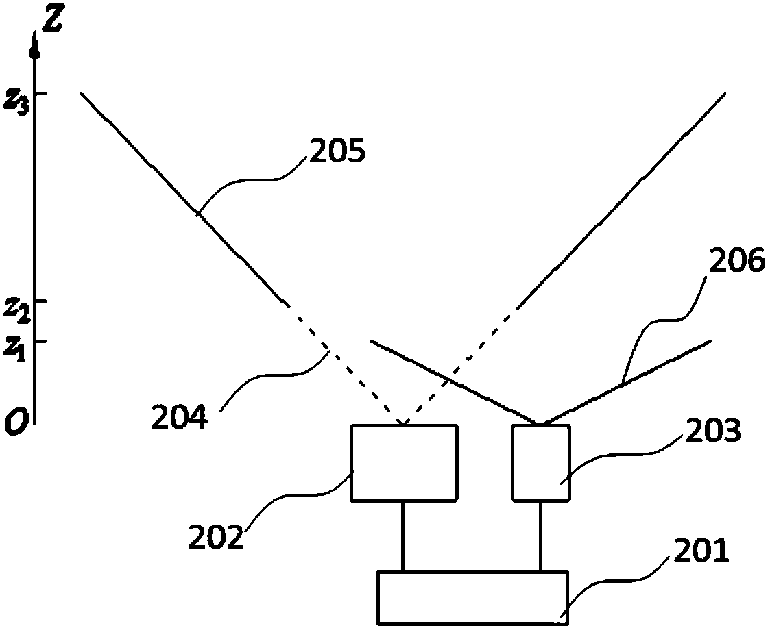
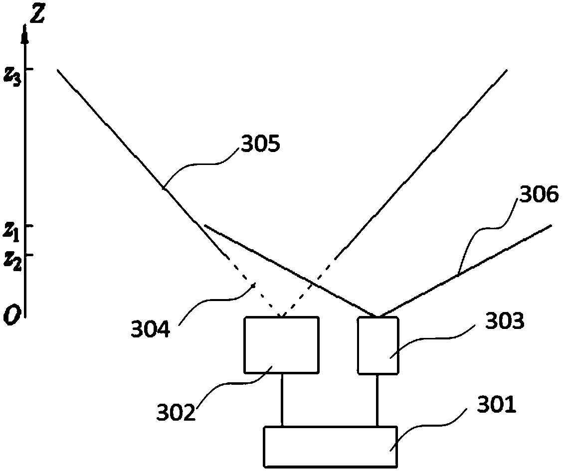
The invention provides a laser safety control method based on a range sensor. The method comprises the following steps: collecting depth image of an object in a first depth range by utilizing a depthcamera comprising a laser light source; detecting the distance of an object in a second depth range by utilizing the rang sensor; and when the distance of the object reaches a risk value, controllingthe laser light source, the lower limit value of the first depth range being smaller than the upper limit value of the second depth range. The invention also provides a laser safety control device based on the range sensor. The laser safety control method and device based on the range sensor can judge whether the depth camera is close enough to the face or is damaged, and control the laser light source according to the judgment result, thereby effectively solving the problem of laser safety of equipment comprising a laser emitter.

Description

technical field [0001] The invention relates to the technical fields of optics and electronics, in particular to a distance sensor-based laser safety control method and device. Background technique [0002] 3D imaging technology can be used in smart devices to realize 3D face recognition, scanning, unlocking and other functions. Compared with fingerprint recognition, 3D face recognition is not only more accurate, but also applicable to a wider range of scenarios. 3D imaging technology based on infrared structured light technology It is not sensitive to light, and can realize skin color detection and three-dimensional detection, and has extremely high face recognition security. [0003] Infrared structured light 3D depth cameras generally include a laser transmitter and a receiver. In order to prevent the laser from harming the human body, a special design is required for the transmitter and a safe use distance must be set to ensure laser safety. However, for integrated 3D de...

Claims


Application Information

Patent Timeline
IPC IPC(8): H01S3/10H01S5/06
CPCH01S3/10H01S5/06
Inventor 许星闫敏
Owner SHENZHEN ORBBEC CO LTD
Learn More