Heat pipe conduction and heat radiation device

A heat dissipation device and heat pipe technology, which is applied in the field of thermal management, can solve the problems of large thermal resistance and low heat dissipation efficiency, and achieve the effects of increasing heat transfer coefficient, prolonging service life, and ensuring working temperature

Pending Publication Date: 2018-03-30
深圳市迈安热控科技有限公司
View PDF7 Cites 2 Cited by
  • Summary
  • Abstract
  • Description
  • Claims
  • Application Information

AI Technical Summary

Problems solved by technology

[0004] The technical problem to be solved by the present invention is to provide a heat pipe conduction and heat dissipation structure in view of the technical defects of large thermal resistance and low heat dissipation efficiency in the prior art that the heat dissipation end of the heat pipe and the water-cooled plate are pasted by heat-conducting silica gel

Method used


Image

  • Heat pipe conduction and heat radiation device
  • Heat pipe conduction and heat radiation device
  • Heat pipe conduction and heat radiation device

Examples


Embodiment Construction

[0031] In order to make the technical problems, technical solutions and beneficial effects solved by the present invention clearer, the present invention will be further described in detail below in conjunction with the accompanying drawings and embodiments. It should be understood that the specific embodiments described here are only used to explain the present invention, not to limit the present invention.

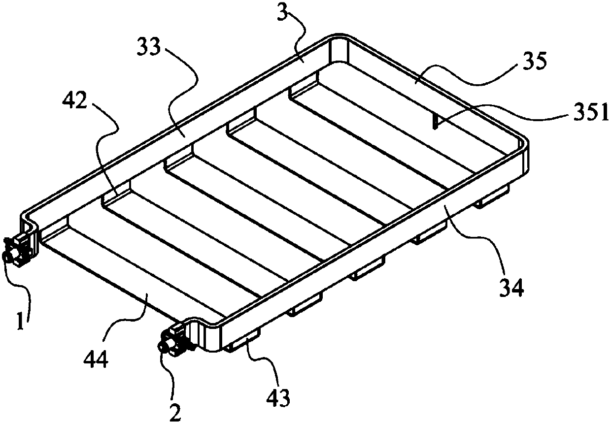
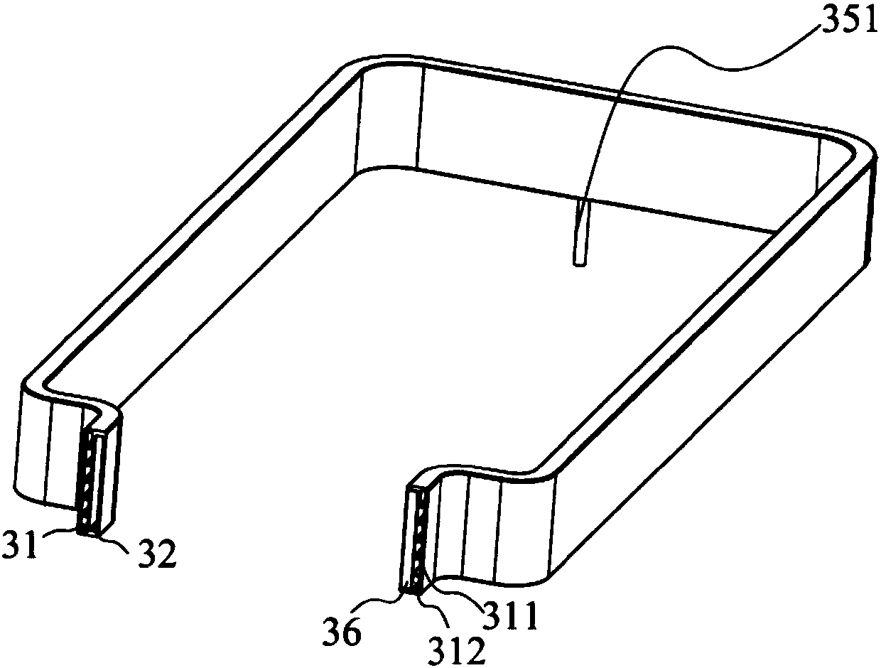
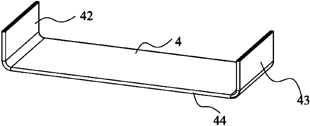
[0032] Such as Figure 1 to Figure 7 As shown, the heat pipe heat dissipation device provided by an embodiment of the present invention includes a water inlet pipe 1, a water outlet pipe 2, a cooling plate 3 and a plurality of pipe bodies 4, and the cooling plate 3 is provided with adjacent first flow channels 31 and The second flow channel 32, the cooling plate 3 includes a first pair of plates 33, a second pair of plates 34 and a connecting plate 35, the first flow channel 31 and the second flow channel 32 pass through the first pair of plates 33 in sequence , the con...


PUM


Abstract

The invention provides a heat pipe conduction and heat radiation device comprising a water inlet pipe, a water outlet pipe, a cooling plate and multiple pipe bodies. The cooling plate is internally provided with a first flow channel and a second flow channel which are adjacent. The first flow channel and the second flow channel penetrate through a first opposite plate, a connecting plate and a second opposite plate in turn. One end of micro-channel holes is communicated with the second flow channel through first openings, and the other end of the micro-channel holes is communicated with the second flow channel through second openings. The phase change medium flows in the second flow channel and multiple micro-channel holes. The cooling liquid flows into the first flow channel from the water inlet pipe and flows out of the water outlet pipe so as to take away the heat of the phase change medium. Therefore, the phase change medium can realize heat exchange with the cooling liquid in thefirst flow channel through the external wall of the second flow channel so that the thermal resistance between the phase change medium and the cooling liquid can be reduced, the heat transfer coefficient can be increased and the heat transfer efficiency can be enhanced. The heat of the power device can be taken away in time so that the normal working temperature of the power device can be guaranteed.

Description

technical field [0001] The invention belongs to the technical field of heat management, and in particular relates to a heat pipe conduction and heat dissipation device. Background technique [0002] In the fields of electric vehicles, industrial electronics, consumer electronics, computer rooms, data servers, etc., equipment or devices will generate a lot of heat when they are working. If this heat cannot be dissipated in time, the temperature of the equipment or the environment will continue to rise. High temperature will seriously affect the operation stability and life of the device, so various thermal managements are required to make the device work within a suitable temperature range. Thermal management includes heat transfer and heat dissipation, one of the heat transfer devices is the porous heat pipe. The porous heat pipe is only a heat conduction device, not a heat dissipation device. To apply the heat pipe to heat dissipation, a certain heat dissipation device mus...

Claims


Application Information

Patent Timeline
Patent Type & Authority Applications(China)
IPC IPC(8): H05K7/20
CPCH05K7/20272H05K7/20327H05K7/20336
Inventor 康笑天
Owner 深圳市迈安热控科技有限公司
Why Eureka
Try Eureka