Low-NO<x> efficient chain grate furnace with function of distributing air by area in width direction of grate

A chain furnace and grate technology, applied in the field of chain furnaces, can solve the problems of poor burnout and coal piles

Inactive Publication Date: 2018-04-03
NINGBO UNIV
View PDF6 Cites 5 Cited by
  • Summary
  • Abstract
  • Description
  • Claims
  • Application Information

AI Technical Summary

Problems solved by technology

[0005] The purpose of the present invention is in order to solve the chain furnace low-oxygen combustion control NO mentioned in the background technology x The problem of coal piled in the middle of the grate and poor burnout caused by the emission and reduction of exhaust smoke loss, and then provides a low NO x High efficiency chain furnace

Method used


Image

  • Low-NO&lt;x&gt; efficient chain grate furnace with function of distributing air by area in width direction of grate
  • Low-NO&lt;x&gt; efficient chain grate furnace with function of distributing air by area in width direction of grate
  • Low-NO&lt;x&gt; efficient chain grate furnace with function of distributing air by area in width direction of grate

Examples


Embodiment approach 1

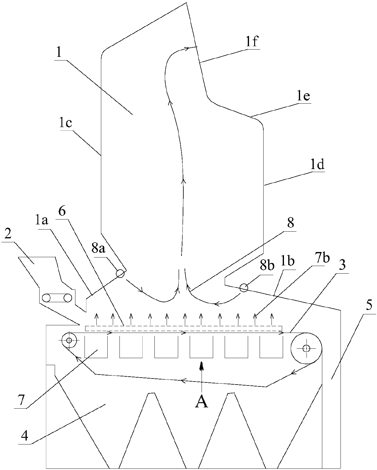
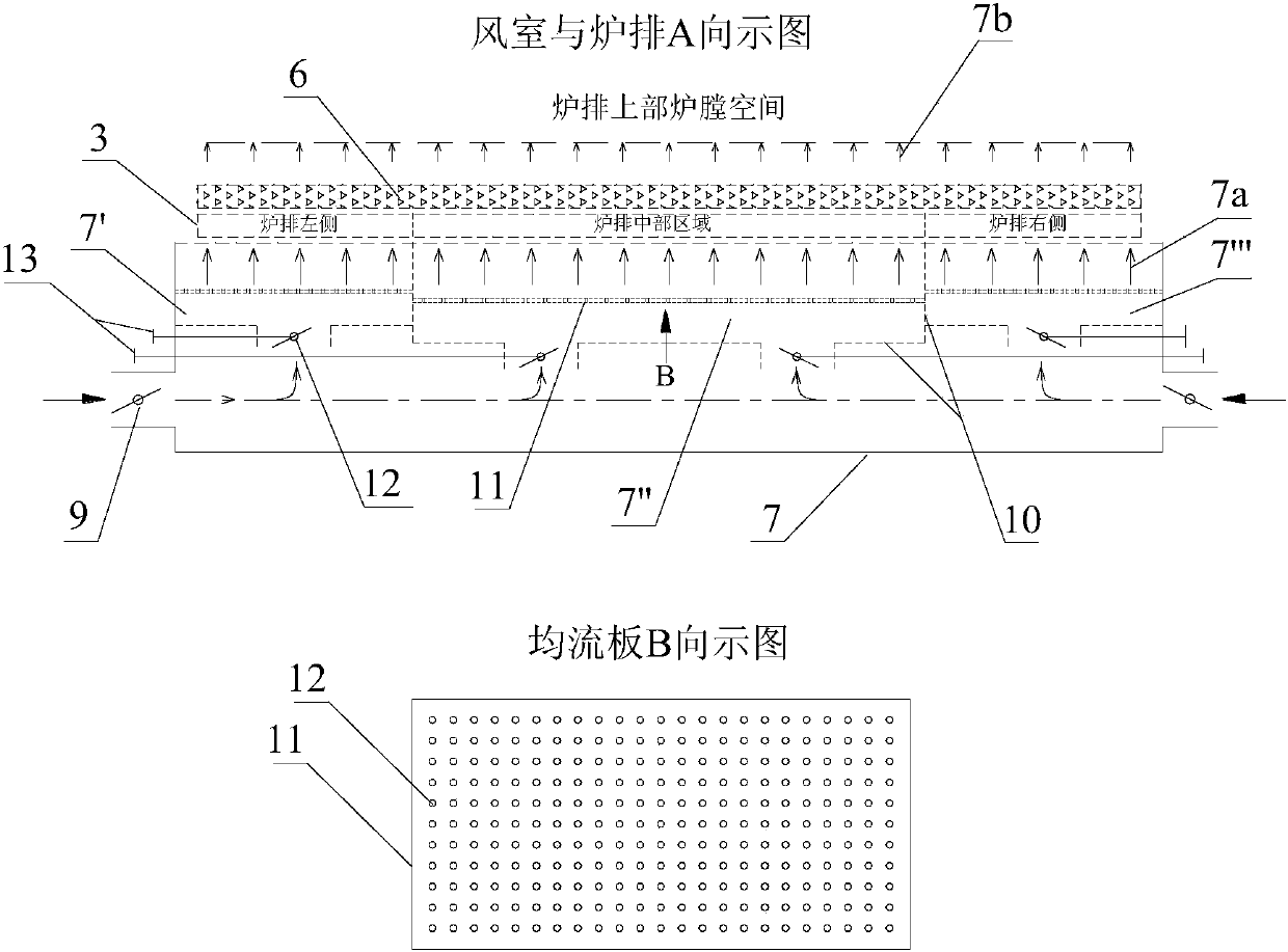
[0014] combine figure 1 and figure 2 Describe this embodiment, a low NO xHigh-efficiency chain furnace, the chain furnace is composed of furnace 1, coal feeder 2, fire grate 3, ash hopper 4 and slag hopper 5; the furnace 1 is composed of front furnace arch 1a, rear furnace arch 1b, front wall 1c, The rear wall 1d, the flame angle 1e and the furnace outlet 1f are composed, and the upper ends of the front furnace arch 1a and the rear furnace arch 1b are provided with waists to divide the furnace 1 into upper and lower parts; The coal feeder 2 provides a certain thickness of coal seam 6 on the fire grate 3, and the thickness of the coal seam 6 gradually becomes thinner due to the combustion process along with the direction of the fire grate 3; the space area wrapped by the fire grate 3 A plurality of primary air chambers 7 arranged in the shape of "one" are arranged, and the outlets of the plurality of primary air chambers 7 communicate with the fire grate 3, and the multiple...

Embodiment approach 2

[0018] combine figure 1 Describe this embodiment, when the low NO x When the high-efficiency chain furnace is a coal thrower chain furnace, the coal feeder 2 adopts the coal thrower 2 arranged on the side of the front wall 1c, and the coal particles are thrown to the rear wall 1d side by the coal thrower 2. A coal seam 6 is formed; the fire grate 3 is an inverted fire grate 3 traveling from the rear wall 1d side to the front wall 1c side; the furnace arch combination is such that only the front furnace arch 1a is provided without the rear Furnace arch 1b, but the layout scheme of the secondary air 8 adopts "the front furnace arch 1a arranges a plurality of the front arch secondary air nozzles 8a, and the lower part of the rear wall 1d arranges a plurality of the rear The secondary air nozzle 8b is arched. Other relevant furnace structure composition, air chamber structure layout and connection relationship are the same as the first embodiment.


PUM


Abstract

The invention discloses a low-NO<x> efficient chain grate furnace with a function of distributing air by area in the width direction of a grate. On the basis that air enters from the two sides of theposition below the grate, a primary air chamber is divided into a grate left air chamber body, a grate middle air chamber body and a grate right air chamber body by subarea partition plates in the width direction of the grate, the grate left air chamber body, the grate middle air chamber body and the grate right air chamber body are three transverse small air chamber bodies, inlets of all the transverse small air chamber bodies are provided with adjustable air doors, flow equalization plates are arranged in the transverse small air chamber bodies, and accordingly, the condition for distributing the air by area in the width direction of the grate is built. The effect that based on the existing technology, air supply of the middle of a coal seam is strengthened, and air supply of the two sides of the coal seam is appropriately reduced, thus, primary air is relatively uniformly distributed in the width direction of the grate, the situation that the air pressure, the air volume and the airflow penetrating power of all the areas of the coal seam are consistent with the air / coal diffusive combustion condition is achieved, surplus escaped air above the coal seam is little and uniform, accordingly, the problem that when NO<x> discharge is controlled through low-oxygen combustion, coal is stacked in the middle of the grate, and as a result, the burnout effect is poor is solved, the efficient low-oxygen combustion condition of the grate areas is built, and the effects of being good in burnout, low in smoke exhaust loss and small in NO<x> generation amount are achieved.

Description

technical field [0001] The invention relates to a chain furnace, in particular to a low NO x A high-efficiency chain furnace belongs to the technical field of chain furnace combustion. Background technique [0002] There are about 600,000 coal-fired industrial boilers in my country, of which chain furnaces account for about 60%. The chain furnace adopts the grate layer combustion method. In order to adapt to the stages of preheating and drying, volatilization analysis and combustion, coke combustion and burnout that the coal seam goes through successively with the grate, it takes into account the control of NO x Formation, the chain furnace divides the large air chamber under the grate into several small primary air chambers in the moving direction of the grate, so as to organize segmental combustion according to the needs of the combustion process. However, in actual operation, in order to ensure that the primary air has a strong penetration to the coal seam on the grate,...

Claims


Application Information

Patent Timeline
Patent Type & Authority Applications(China)
IPC IPC(8): F23L1/02F23L3/00F23M5/06F23L9/00F23B30/08
CPCF23L1/02F23B30/08F23L3/00F23L9/00F23M5/06
Inventor 况敏杨国华尚政伟胡雪慧
Owner NINGBO UNIV
Why Eureka
Try Eureka