
Self-propelled marine visual grab bucket and sampling ship adopting same

A self-propelled, grab bucket technology, applied in the field of self-propelled marine visible grab bucket and its sampling vessel, can solve the problems of hydraulic system failure in the grab bucket, easy damage of the towing device, and impact by the sea current, etc. The ability of sea current impact, corrosion resistance, wear resistance, repeated retraction, good mechanical strength

Pending Publication Date: 2018-04-03
SHANDONG UNIV
View PDF0 Cites 10 Cited by
  • Summary
  • Abstract
  • Description
  • Claims
  • Application Information

AI Technical Summary

Problems solved by technology

At present, when sampling, the staff usually sets the target position in advance on the sampling ship and then sinks the grab into the water to grab samples. This method is easily affected by ocean currents, such as grabbing when lowering the grab The bucket will be impacted by the ocean current, which will affect its normal lowering; after the grab bucket sinks into the seabed, the hydraulic system in the bucket will fail due to the change of underwater pressure; and when the bucket is working under the sea, it often encounters schools of fish interference; when the sea is rough, the connection between the towing device on the sampling ship and the grab will be tested; the position changes of the sampling ship and the underwater grab will constantly bring different sizes of the towing device on the hull. The pulling force makes the towing device extremely easy to damage

Method used


Image

  • Self-propelled marine visual grab bucket and sampling ship adopting same
  • Self-propelled marine visual grab bucket and sampling ship adopting same
  • Self-propelled marine visual grab bucket and sampling ship adopting same

Examples


Embodiment Construction

[0027] In order to clearly illustrate the technical features of this solution, the present invention will be described in detail below through specific implementation modes and in conjunction with the accompanying drawings.

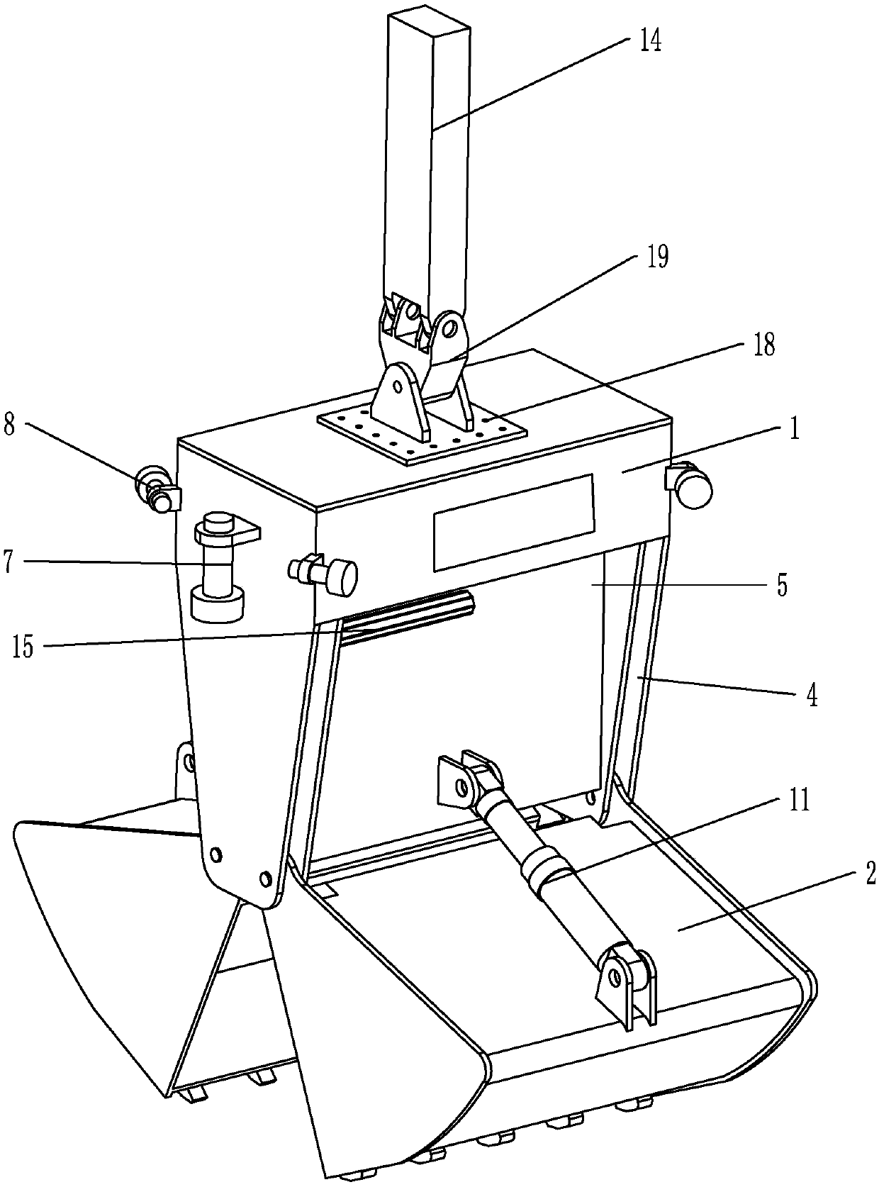
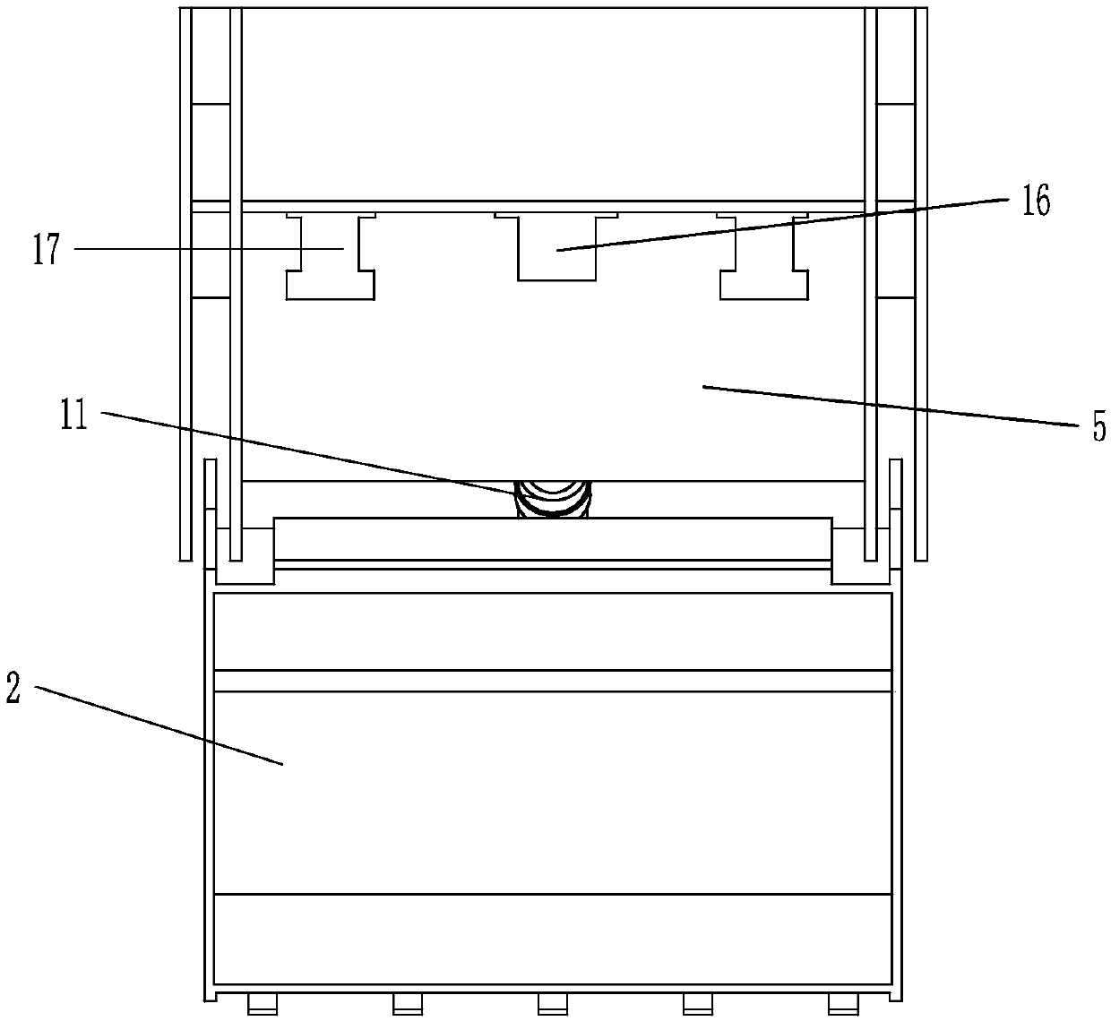
[0028] Such as Figure 1-6 As shown in , a self-propelled marine visible grab includes a grab installation main body 1 and two grab buckets 2 symmetrically hinged on the lower part of the grab installation main body 1. The upper part of the grab installation main body 1 is a sealed Two pairs of mounting lugs 4 are arranged opposite to each other on both sides of the bottom of the cabin 3 and the sealed cabin 3, and two installation base plates 5 are arranged in parallel between the two pairs of grabbing bucket mounting lugs 4; The ear plate 4 is hinged, and the tops of the two grabs 2 are respectively hinged with the installation base plate 5 through a grab opening and closing hydraulic cylinder 6;

[0029] Two relative outer walls of the sealed cabin 3 ...


PUM


Abstract

The invention discloses a self-propelled marine visual grab bucket and a sampling ship adopting the same. The self-propelled marine visual grab bucket comprises a grab bucket installation main body and two grab buckets symmetrically hinged to the lower part of the grab bucket installation main body, wherein a sealed cabin is arranged at the upper part of the grab bucket installation main body; anupper submersible propeller is horizontally arranged on each of two opposite external side walls of the sealed cabin; a circumferential propeller is vertically arranged at each of four side edges of the sealed cabin; a buoyancy control device, a pressure compensation device and a grab bucket hydraulic system which is connected with a grab bucket opening and closing hydraulic cylinder are arrangedin the sealed cabin. According to the self-propelled marine visual grab bucket and the sampling ship adopting the same, signals collected by a camera and a deep-sea sensor are transmitted to a controlroom through an armored cable, so that workers can observe and detect a sampling area firstly, the position and posture of the grab bucket are adjusted by regulation and control of a computer controlsystem and an operator, the current impact resistance capability of the device is improved, and the operation stability and reliability of the grab bucket are improved.

Description

Technical field: [0001] The invention belongs to the field of deep sea sampling equipment, in particular to a self-propelled ocean visual grab and a sampling ship thereof. Background technique: [0002] With the continuous advancement of science and technology, people's exploration and research on the sea is also advancing. Among them, deep-sea sampling and marine scientific research including ore, seabed soil, seabed combustible ice and other seabed sediments require the use of scientific research ships to take samples to the sea surface. At present, when sampling, the staff usually set the target position in advance on the sampling ship and then sink the grab into the water to grab samples. This method is easily affected by ocean currents, such as grabbing when lowering the grab. The bucket will be impacted by the ocean current, which will affect its normal lowering; after the grab bucket sinks into the seabed, the hydraulic system in the bucket will fail due to the chang...

Claims


Application Information

Patent Timeline
IPC IPC(8): G01N1/04
CPCG01N1/04
Inventor 刘延俊薛钢李世振陈志孟忠良武爽杨晓玮
Owner SHANDONG UNIV
Learn More