Micro element feeder

A technology of micro-components and feeders, applied in the direction of electrical components, electrical components, etc., can solve the problems of expensive products, side-standing materials, poor feeding, etc., to ensure stability and stability, ensure feeding stability, The effect of extending the service life

Pending Publication Date: 2018-04-03
JIUJIANG JIAYUAN TECH
View PDF0 Cites 0 Cited by
  • Summary
  • Abstract
  • Description
  • Claims
  • Application Information

AI Technical Summary

Problems solved by technology

At present, FEEDER abroad is using the principle of mechanical transmission to ensure stable feeding and accurate feeding position. The reverse side of the parts, the automatic stripping of the material tape packaging cannot be effectively carried out, and the disadvantages are magnetic.
Due to the backward technology and processing equipment in China, it is currently impossible to produce FEEDER that meets the technical requirements, and can only be imported from countries such as Europe, America or Japan.

Method used


Image

  • Micro element feeder
  • Micro element feeder
  • Micro element feeder

Examples


Embodiment Construction

[0023] Below in conjunction with accompanying drawing and present embodiment the present invention is further described:

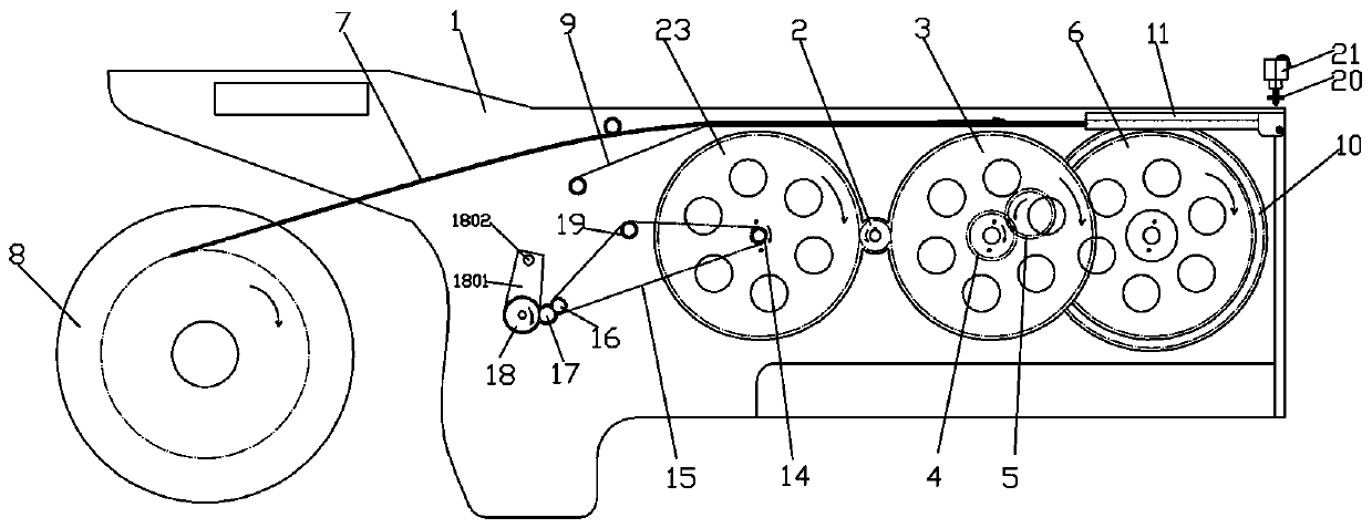
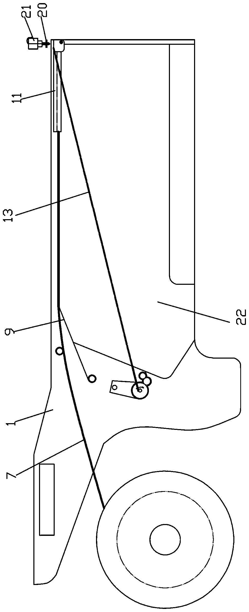
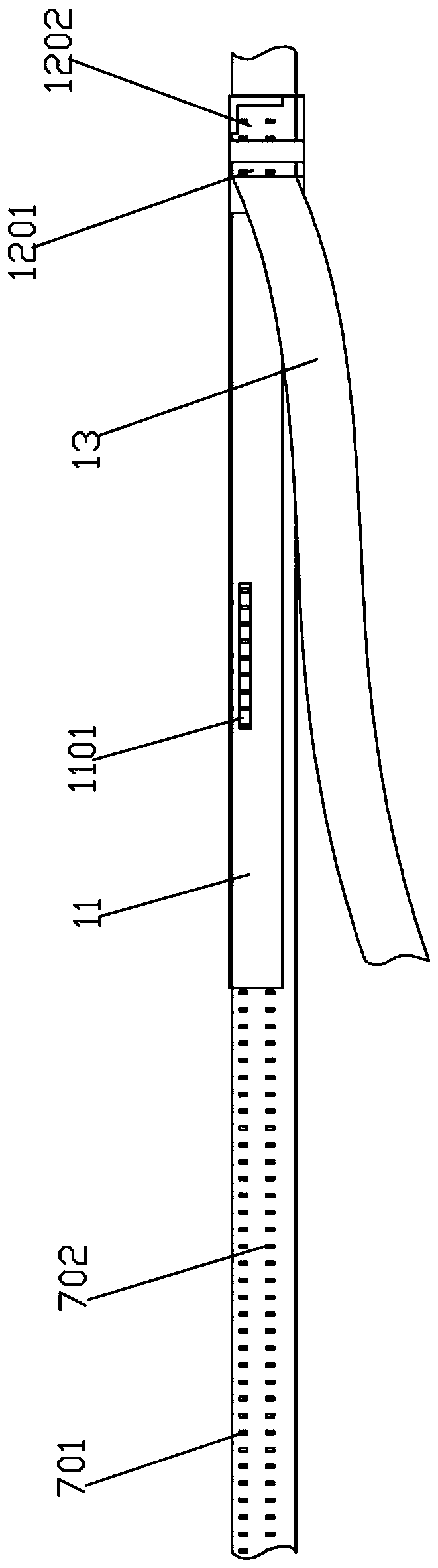
[0024] see Figure 1-4 .

[0025] The invention discloses a micro-component feeder, which includes a housing 1, and a conveying paper belt 7 for transferring micro-components is arranged on the upper side of the housing 1. The support plate 9 extending in the direction is used to support the conveying paper belt. One side of the housing 1 is provided with a material rack 8 for installing a paper roll. The conveying paper belt 7 is disc-shaped and wound on the material rack 8 On the rotating shaft in the middle, after the paper roll is installed on the material rack 8, one end of the conveying paper belt 7 is pulled out and placed on the support plate 9, and a row of conveying holes 701 and a row of miniature The placement groove 702 of the component, the miniature components are installed in the placement groove 702 one by one, and the transmission holes...


PUM


Abstract

The invention relates to a micro-element feeder, which includes a housing, and a conveying paper belt for transferring micro-elements is arranged above the housing, and a support extending along the conveying direction of the paper tape for supporting the conveying paper tape is arranged in the housing One side of the housing is provided with a material rack for installing paper rolls, and a row of transmission holes and a row of micro-component placement grooves are provided on the transmission paper belt. The transmission holes and the placement grooves are both along the transmission direction of the transmission paper belt. Extend and arrange in sequence at equal intervals; there are transmission gears rotating at intervals in the housing, the rotation direction of the transmission gear is the same as the transmission direction of the transmission paper belt, and the tooth tips of the transmission gears are inserted into the transmission holes of the transmission paper belt in turn and It is transmitted forward at a constant speed and at equal intervals, and a suction device for micro components is installed above the placement groove. In the transmission gap, the suction device sucks and transfers the micro components. The present invention uses multiple groups of gears for transmission, which ensures the smoothness and stability of the transmission process.

Description

technical field [0001] The invention relates to the technical field of electronic component production and transfer equipment, in particular to a micro component feeder. Background technique [0002] FEEDER (micro component feeder) is an important part of the placement machine in the SMT industry. The most prerequisite for accurate placement is to design a feeder that matches it, and to be able to achieve the accuracy and speed of picking up electronic components required by the equipment . To meet the purpose of accurate pickup and placement of the placement machine. In recent years, with the rapid development of the technical field of electronic components, there are more and more types of chip electronic components, and the size is getting smaller and smaller, which has developed from 0402 type to 0201 type. The requirements for FEEDER are getting higher and higher. At present, FEEDER abroad is using the principle of mechanical transmission to ensure stable feeding and...

Claims


Application Information

Patent Timeline
Patent Type & Authority Applications(China)
IPC IPC(8): H05K13/04
CPCH05K13/0417H05K13/0408H05K13/046
Inventor 冯思忆冯韵涵唐子康
Owner JIUJIANG JIAYUAN TECH
Why Eureka
Try Eureka