Connecting rod big end hole integral machining device
A technology of integral processing and big head holes, which is applied in the direction of positioning devices, metal processing equipment, metal processing machinery parts, etc., can solve the problems of affecting the quality of connecting rods, low processing efficiency, poor consistency of big head hole processing dimensions, etc., to improve product quality , Improving processing efficiency and reasonable structural design
- Summary
- Abstract
- Description
- Claims
- Application Information
AI Technical Summary
Problems solved by technology
Method used
Image

Examples
Embodiment Construction
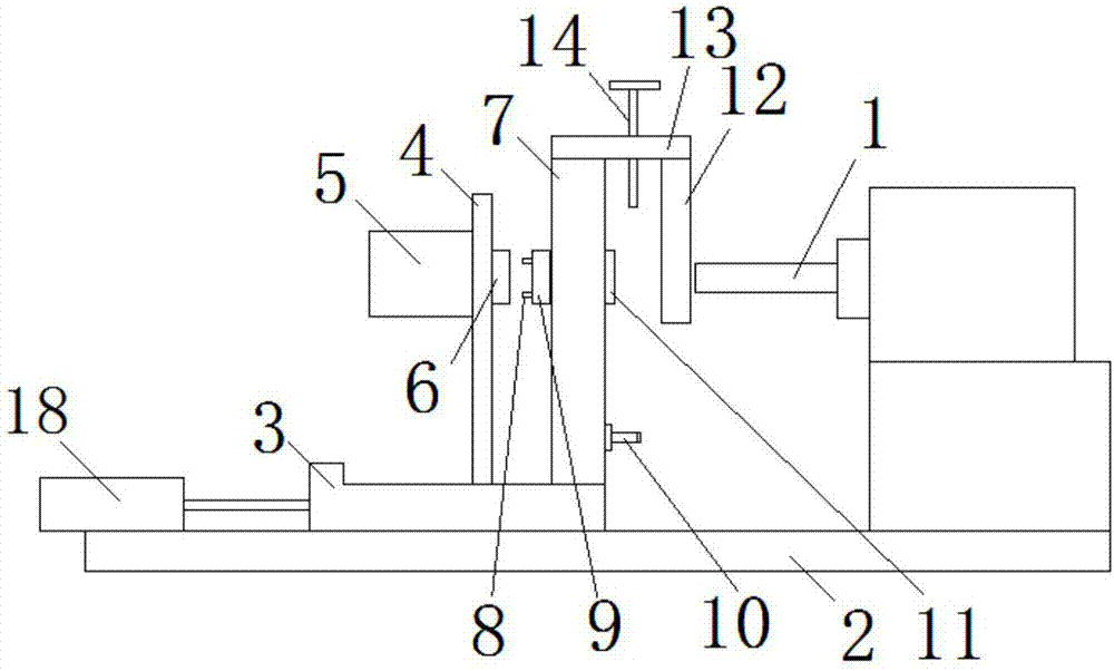
[0022] The specific implementation manner of the present invention will be described in further detail below by describing the embodiments with reference to the accompanying drawings.
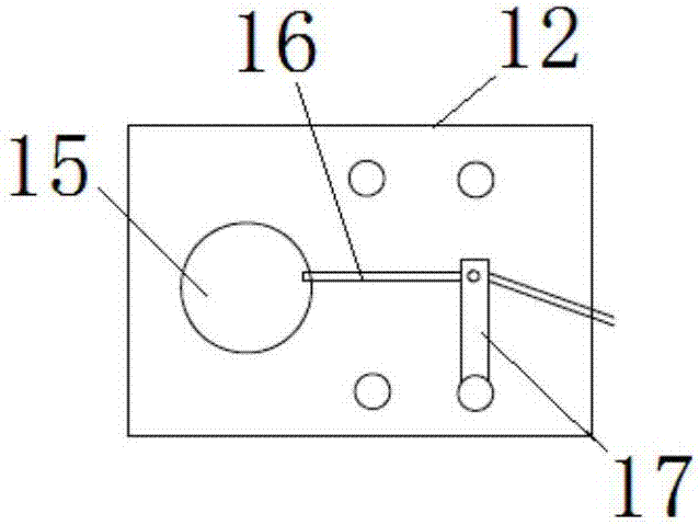
[0023] Such as figure 1 and figure 2 As shown, the overall processing device for the big head hole of the connecting rod includes a boring head 1, a bottom plate 2, a sliding plate 3, a support plate 4, a hydraulic cylinder 5, a piston head 6, a fixed plate 7, a top column 8, a top block 9, Connecting rod small end positioning column 10, movable briquetting block 11, baffle plate 12, top plate 13, pressure rod 14, air blowing pipe 16, support rod 17 and working cylinder 18.
[0024] The bottom plate 2 is provided with a connecting rod positioning mechanism for fixing the connecting rod body and the connecting rod cover and a boring machine for boring the big hole of the connecting rod. The boring machine is provided with a boring cutter head 1 .
[0025] The boring machine and the connecting...
PUM
 Abstract
Description
Claims
Application Information
 - Generate Ideas
- Intellectual Property
- Life Sciences
- Materials
- Tech Scout
- Unparalleled Data Quality
- Higher Quality Content
- 60% Fewer Hallucinations
Browse by: Latest US Patents, China's latest patents, Technical Efficacy Thesaurus, Application Domain, Technology Topic, Popular Technical Reports.
© 2025 PatSnap. All rights reserved.Legal|Privacy policy|Modern Slavery Act Transparency Statement|Sitemap|About US| Contact US: help@patsnap.com