Air conditioning system for vehicle and vehicle
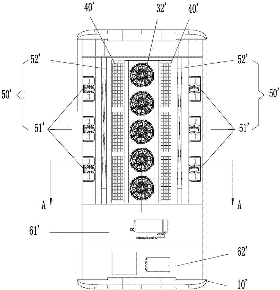
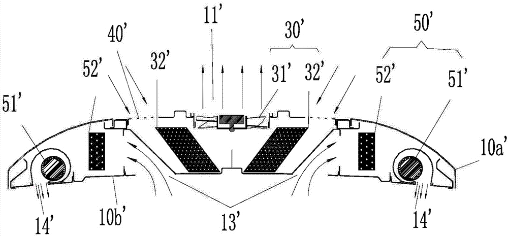
An air-conditioning system and vehicle technology, applied to the vehicle's air-conditioning system and the field of vehicles, can solve problems such as unfavorable defrosting of the condenser 32', large air supply resistance, disadvantages, etc., achieve good cooling and heating effects, convenient installation and The effect that maintenance, installation space is wide
- Summary
- Abstract
- Description
- Claims
- Application Information
AI Technical Summary
Problems solved by technology
Method used
Image
Examples
Embodiment 1
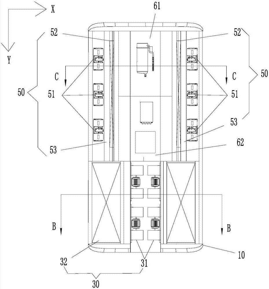
[0036] Such as image 3 As shown, the present invention provides an air conditioning system for a vehicle, the vehicle includes a vehicle body, the air conditioning system is arranged on the vehicle body, the air conditioning system includes a second heat exchanger assembly 50 and a first heat exchanger assembly 30, wherein, in the vehicle In the longitudinal direction of the body, the second heat exchanger assembly 50 and the first heat exchanger assembly 30 are arranged one behind the other.
[0037] Through the above arrangement, it is ensured that the second heat exchanger assembly 50 and the first heat exchanger assembly 30 have sufficient arrangement space. At the same time, the air conditioning system is located on the top of the car body, which is convenient for installation and maintenance. Compared with the prior art where the second heat exchanger assembly 50 is arranged on both sides of the first heat exchanger assembly 30, the layout of the present application is...
Embodiment 2
[0076] Such as Figure 7 As shown, it is an alternative arrangement of the first heat exchanger assembly 30 , and the installation positions of the first heat exchanger 32 and the first fan 31 are adjusted on the basis of the first arrangement.
[0077] The difference from Embodiment 1 is that, as Figure 7As shown, the first heat exchanger 32 can be set so that the side close to the first fan 31 is low, and the side close to the first air outlet 11 is high, arranged in an inverted "eight" shape, and the air outlet section of the first fan 31 The upper part is close to the top plate 10a of the air conditioner body 10, so that the air outlet section of the first fan 31 and the first air outlet 11 of the first heat exchanger 32 are on the same horizontal plane, and there is no height difference, which is more conducive to the smooth flow of airflow.
[0078] Due to the "sticking effect" of the air flow, the cross-sectional area of the air outlet section of the first fan 31 gr...
Embodiment 3
[0082] Such as Figure 8 As shown, different from Embodiment 1, the installation positions of the first heat exchanger 32 and the first fan 31 are adjusted, the two first heat exchangers 32 are arranged in a "V" shape structure, and the first heat exchanger 32 Compared with the first blower 31, it is closer to the first air inlet 40, which can ensure smooth air outlet and less wind resistance. Specifically, the first heat exchanger 32 is moved to directly below the top cover 20 , and the first fan 31 is moved to a side of the first heat exchanger 32 facing the first air outlet 11 . In this arrangement, the airflow entering from the first air inlet 40 passes through the first heat exchanger 32 first, and then is discharged through the first blower 31 .
[0083] The rest of the structure is the same as the first embodiment of the present application, and will not be repeated here.
PUM
 Abstract
Description
Claims
Application Information
 - R&D
- Intellectual Property
- Life Sciences
- Materials
- Tech Scout
- Unparalleled Data Quality
- Higher Quality Content
- 60% Fewer Hallucinations
Browse by: Latest US Patents, China's latest patents, Technical Efficacy Thesaurus, Application Domain, Technology Topic, Popular Technical Reports.
© 2025 PatSnap. All rights reserved.Legal|Privacy policy|Modern Slavery Act Transparency Statement|Sitemap|About US| Contact US: help@patsnap.com


