Rope-salvage-type torsion impact coring drilling tool

A technology of core drilling tools and ropes, which is applied in the direction of extracting undisturbed core devices, earth square drilling, and vibration drilling, etc. It can solve problems such as stick-slip vibration, reduce core blockage, reduce auxiliary operation time, and improve rock breaking efficiency Effect

Pending Publication Date: 2018-04-06
EXPLORATION TECH RES INST OF CHINESE ACADEMY OF GEOLOGICAL SCI
0 Cites 0 Cited by

AI-Extracted Technical Summary

Problems solved by technology

[0004] The invention provides a rope salvage type torsional percussion core drilling tool, which aims to solve the problem of stick-slip vibration of the lower drilling tool during the...

Abstract

A rope-salvage-type torsion impact coring drilling tool comprises an inner pipe assembly and an outer pipe assembly. A drill bit is arranged at the lower end of the outer pipe assembly, and the innerpipe assembly is sleeved with the outer pipe assembly. A salvage assembly, a turbine assembly, a torsion impact generating assembly, a torsion impact transmitting assembly and a sampling pipe assemblyare sequentially arranged from top to bottom. The turbine assembly is driven through well drilling liquid to rotate, and the torsion impact generating assembly is provided with an impact shaft whichis connected with the power output end of the turbine assembly. An impact block is assembled in the impact shaft, and the impact shaft is sleeved with an impact pipe. A boss structure is arranged on the inner wall of the impact pipe, and the impact block periodically collides the boss structure of the impact pipe along with rotation of the impact shaft to generate torsion impact force. The torsionimpact force is transmitted to the drill bit through the torsion impact transmitting assembly. According to the rope-salvage-type torsion impact coring drilling tool, the problem of stick-slip oscillation of the lower portion of a drilling tool in the deep well and ultra-deep well coring drilling process is solved, and the purposes that the drilling speed is increased, the number of times of large drill lifting is decreased, and the working efficiency is improved are achieved.

Application Domain

Vibration drillingCore removal

Technology Topic

Drill bitRotation cycle +4

Image

  • Rope-salvage-type torsion impact coring drilling tool
  • Rope-salvage-type torsion impact coring drilling tool
  • Rope-salvage-type torsion impact coring drilling tool

Examples

  • Experimental program(1)

Example Embodiment

[0038] The present invention will be further described below with reference to the accompanying drawings and specific embodiments.
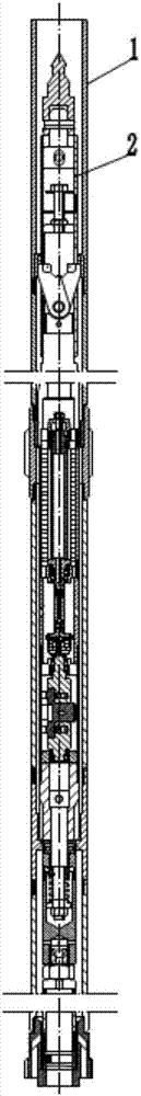
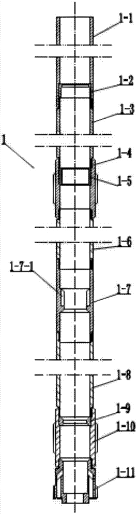
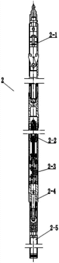
[0039] see figure 1 , figure 2The present invention provides a rope fishing type torsional impact coring drill, which includes an outer tube assembly 1 and an inner tube assembly 2; the inner tube assembly 2 is sheathed in the inner cavity of the outer tube assembly 1. The outer pipe assembly 1 is composed of an upper connecting pipe 1-1, a snap stop head 1-2, an upper outer pipe 1-3, an upper reamer 1-4, a water blocking ring 1-5, and middle and outer pipes. 1-6. Twist transmission joint 1-7, lower outer tube 1-8, centralizing ring 1-9, lower reamer 1-10 and drill bit 1-11 are connected by thread; snap stop head 1-2 is embedded in the upper In the inner cavity of the connecting pipe 1-1, it is limited by the threads of the upper connecting pipe 1-1 and the upper outer pipe 1-3; the water blocking ring 1-5 is embedded into the inner cavity of the upper reamer 1-4 , at the same time through the threads of the upper outer tube 1-3 and the upper reamer 1-4 to be tightened and then pressed; After tightening with the thread of the lower reamer 1-10, it is limited; the drill bit 1-11 is a PDC drill bit.
[0040] see image 3 , In the rope fishing type torsional impact coring drill provided by the present invention, the inner tube assembly 2 is sequentially provided with a salvage component 2-1, a turbine component 2-2, a torsional impact generating component 2-3, a torsion component 2-3 from top to bottom Shock transfer assembly 2-4 and sampling tube assembly 2-5.
[0041] see Figure 4 , In the rope salvage type torsional impact coring drill provided by the present invention, the salvage component 2-1 is provided with a fishing spearhead 2-1-1, a spring clip mechanism 2-1-2 and a single-action bearing 2-1-3; The spear fishing head 2-1-1 is matched with the rope salvage device; the spring clip mechanism 2-1-2 cooperates with the bullet clip blocking head 1-2 of the outer tube assembly 1 to realize the axial locking of the inner tube assembly 2 The single-acting bearing 2-1-3 is sleeved on the clip mechanism 2-1-2, and is used to realize the relative rotation between the salvage assembly 2-1 and the turbine assembly 2-2.
[0042] see Figure 5 , the rope salvage type torsional impact coring drill provided by the present invention, the turbine assembly 2-2 includes a liquid inlet pipe 2-2-1, a turbine stator 2-2-2, a turbine rotor 2-2-5, a liquid outlet pipe 2-2-1 Pipe 2-2-3 and universal joint 2-2-4; the side wall of the liquid inlet pipe 2-2-1 is provided with a liquid inlet hole 2-2-1-1, and the liquid inlet pipe 2-2-1 The upper end is connected with the salvage component 2-1, and the lower end is connected with the liquid outlet pipe 2-2-3; the turbine stator 2-2-2 and the turbine rotor 2-2-5 are assembled and then sleeved on the liquid inlet pipe 2-2-1 In the inner cavity of the liquid outlet pipe 2-2-3 is provided with a liquid outlet hole 2-2-3-1 on the side wall; a universal joint 2-2-4 is installed under the turbine rotor 2-2-5 , the universal joint 2-2-4 is connected with the torsional impact generating assembly 2-3.
[0043] see Figures 6 to 10 , In the rope fishing type torsional impact coring drill provided by the present invention, the torsional impact generating assembly 2-3 includes an upper end cover 2-3-1, an impact shaft 2-3-2, an impact block 2-3-3, Compression spring 2-3-4, guide block 2-3-5, lower end cover 2-3-6 and impact tube 2-3-7; the impact shaft 2-3-2 is set inside the impact tube 2-3-7 , the upper end cap 2-3-1 and the lower end cap 2-3-6 are fitted on both ends of the impact shaft 2-3-2, and the upper end cap 2-3-1, the lower end cap 2-3-6 and the impact shaft 2 The bearing is installed between -3-3, the impact block accommodating cavity 2-3-2-1 is arranged in the middle part of the impact shaft 2-3-2, and the left and right sides of the impact block accommodating cavity 2-3-2-1 are symmetrically arranged Two sets of spring accommodating chambers 2-3-2-2; the impact block 2-3-3 is placed in the impact block accommodating chamber 2-3-2-1, and the impact block 2-3-3 is provided with an impact portion 2- 3-3-2 and the radial movement driving part 2-3-3-1 located on both sides of the impact part, the impact part 2-3-3-2 is provided with a central long groove 2-3-3-3, the impact part 2-3-3-3 The block 2-3-3 is installed in the impact block accommodating cavity 2-3-2-1 of the impact shaft 2-3-2 through the center long groove 2-3-3-3 in cooperation with the pin shaft 2-3-8; The compression spring 2-3-4 is placed in the spring accommodating cavity 2-3-2-2, one end of which is fixed at the bottom of the spring accommodating cavity 2-3-2-2, and the other end is against the impact block 2-3-3 on the radial movement driving part 2-3-3-1; the guide block 2-3-5 is fixed on the inner wall of the impact tube 2-3-7, and is provided with a half moon matched with the impact block 2-3-3 Tooth guide surface.
[0044] see Figure 11 , the rope fishing type torsional impact coring drill provided by the present invention, the torsional impact transmission assembly 2-4 includes a torsion transmission tube 2-4-1, a mandrel 2-4-2 and a torque transmission tube single-action bearing 2- 4-3, the upper end of the torque transmission tube 2-4-1 is connected to the impact tube 2-3-7 of the torsional impact generating assembly 2-3, and the outer wall of the torque transmission tube 2-4-1 is provided with a The external splines 2-4-1-1 matched with the assembly 1, the mandrel 2-4-2 is set in the torque transmission tube 2-4-1, and two sets of torque transmission are set outside the mandrel 2-4-2 The tube single-action bearing 2-4-3 realizes the relative rotation of the torsional impact transmission assembly 2-4 and the sampling tube assembly 2-5 through the torsion transmission tube single-action bearing 2-4-3.
[0045] see Figure 1 to Figure 11 The present invention is a rope salvage type torsional impact coring drilling tool, and its working process mainly includes two parts: normal drilling and coring operation. During the drilling process, the inner tube assembly 2 is fitted into the outer tube assembly 1, and the inner tube assembly 2 is positioned axially through the following two positions:
[0046] 1. The clip mechanism 2-1-2 of the salvage component 2-1 in the inner tube assembly 2 is opened and then stuck in the clip head 1-2 of the outer tube assembly 1;
[0047] 2. The lower end of the torsion transmission tube 2-4-1 of the torsional impact transmission component 2-4 in the inner tube assembly 2 is located inside the torque transmission joint 1-7 of the outer tube assembly 1. Splines 1-7-1 on. The drilling fluid flows through the turbine assembly 2-2, thereby driving the turbine assembly 2-2 to rotate, and the turbine assembly 2-2 drives the impact shaft 2-3-2 in the torsional impact generating assembly 2-3 to rotate, which is installed on the impact shaft 2-3 The impact block 2-3-3 on the -2 periodically hits the inner wall boss structure 2-3-7-1 of the impact tube 2-3-7 to generate a torsional impact force, and then the torsional impact is transmitted by the torsional impact transmission component 2-4. The force is transmitted to the drill bit 1-11 of the outer tube assembly 1, thereby applying an additional high-frequency impact force with a uniform and stable rotation direction to the drill bit 1-11, improving the rock crushing efficiency of the drill bit 1-11, and at the same time, the core enters the sampling tube. inside components 2-5. During the coring operation, the spearhead 2-1-1 is lifted up by the fisher, and the clip mechanism 2-1-2 is recovered to realize the positioning and unlocking of the upper part of the drilling tool. -4-1 external spline 2-4-1-1 and the internal spline 1-7-1 of the transmission twist joint 1-7 in the outer assembly 1 are separated, and the core and inner tube assembly 2 can be smoothly lifted Drill pipe inner hole.
[0048] see Figure 12 to Figure 21 , the working process of the torsional impact generating assembly 2-3 is as follows: In the first step, the impact shaft 2-3-2 drives the impact block 2-3-3 to rotate, and the radial movement of the impact block 2-3-3 drives the part 2 -3-3-1 rotates along the crescent-shaped inner wall of the guide block 2-3-5, while compressing the compression spring 2-3-4 installed between the impact block 2-3-3 and the impact shaft 2-3-2 (as attached Figure 12 shown), to make the impact part 2-3-3-2 of the impact block 2-3-3 protrude from the impact block accommodating cavity 2-3-2-1 of the impact shaft 2-3-2 (as shown in the appendix). Figure 13 in the second step, when the radial movement driving part 2-3-3-1 of the impact block 2-3-3 moves to the tail of the guide block 2-3-5 (as shown in the appendix) Figure 14 shown), the impact part 2-3-3-2 of the impact block 2-3-3 hits the boss structure 2-3-7-1 of the impact tube 2-3-7 to realize a torsional impact vibration (as attached Figure 15 In the third step, after the radial movement of the impact block 2-3-3, the drive part 2-3-3-1 turns over the tail of the guide block 2-3-5, the impact block 2-3-3 is compressed Move up under the action of spring 2-3-4 (as attached Figure 16 shown), the impact part 2-3-3-2 moves radially under the cooperation of the central long groove 2-3-3-3 and the pin 2-3-8, and the impact part 2-3-3-2 quickly retracts to In the impact block accommodating chamber 2-3-2-1 (as attached Figure 17 shown); the fourth step, the impact block 2-3-3 continues to rotate (as attached Figure 18 , Figure 19 shown), when the impact part 2-3-3-2 of the impact block 2-3-3 hits the boss structure 2-3-7-1 of the impact tube 2-3-7, the secondary torsion is realized shock vibration (as attached Figure 20 , Figure 21 shown).

PUM

no PUM

Description & Claims & Application Information

We can also present the details of the Description, Claims and Application information to help users get a comprehensive understanding of the technical details of the patent, such as background art, summary of invention, brief description of drawings, description of embodiments, and other original content. On the other hand, users can also determine the specific scope of protection of the technology through the list of claims; as well as understand the changes in the life cycle of the technology with the presentation of the patent timeline. Login to view more.

Similar technology patents

Turbo-type high-frequency pulse pressurizer

PendingCN107355182AImprove rock breaking efficiencyLower Drilling Costs
Owner:YANGTZE UNIVERSITY

Underground sliding sealing tool, infinite extension drilling device and drilling method thereof

PendingCN106499334ASave the surface area of ​​the well siteImprove rock breaking efficiency
Owner:HISPEED WUHAN PETROLEUM TECH CO LTD

Full-section telescopic cutter head structure for vertical shaft heading machine

PendingCN112253127AImprove rock breaking efficiencySmall well offset
Owner:辽宁三三工业有限公司

PDC drill bit with telescopic cutting auxiliary tooth assembly and using method

ActiveCN113882809AImprove rock breaking efficiencyincrease drilling speed
Owner:SHANDONG JINRUI PETROLEUM EQUIP CO LTD

Hydraulic deepening drilling tool

ActiveCN109779528AImprove rock breaking efficiencyIncrease impact range
Owner:CHINA UNIV OF PETROLEUM (BEIJING)

Classification and recommendation of technical efficacy words

  • Improve rock breaking efficiency

Multi-blade multi-angle rock breaking device for rock ripper

InactiveCN102445336Aaccurate measurementImprove rock breaking efficiency
Owner:SHENYANG HEAVY MACHINERY GROUP

Lithology identification based mechanical-hydraulic combined rock breaking TBM real-time tunneling method

ActiveCN110318765AReduce energy consumptionImprove rock breaking efficiency
Owner:INST OF ROCK AND SOIL MECHANICS - CHINESE ACAD OF SCI

Pulsed-jet longitudinal impactor

InactiveCN106703686AImprove rock breaking efficiencyReduce intermediate loss
Owner:BC P INC CHINA NAT PETROLEUM CORP +1

Axial double-acting hydraulic impactor

PendingCN106917582AImprove rock breaking efficiencyImprove drilling efficiency
Owner:YANGTZE UNIVERSITY

High-voltage pulse discharge-mechanical combined rock-breaking full-section tunneling machine

ActiveCN109488316AImprove rock breaking efficiencyReduced tool wear
Owner:CHINA RAILWAY ENGINEERING EQUIPMENT GROUP CO LTD
Why Eureka
Try Eureka