
Pressure energy recycling equipment and pipeline pressure energy recycling system

A technology for recovering equipment and pressure energy, applied in mechanical equipment, steam engine installations, machines/engines, etc., can solve the problems of loss of pressure energy, low degree of system integration, complex process, etc., to reduce failure rate, high degree of integration, The effect of quick installation and commissioning

Pending Publication Date: 2018-04-06
北京大臻科技有限公司
View PDF0 Cites 4 Cited by
  • Summary
  • Abstract
  • Description
  • Claims
  • Application Information

AI Technical Summary

Problems solved by technology

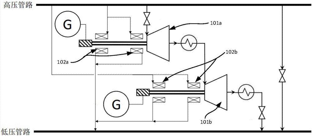
However, the disadvantage of this design is that the process is complicated and the degree of system integration is low. Since each turboexpander 101a or 101b is equipped with two sets of static pressure gas bearings 102a or 102b, the existing turboexpander will Multiple sets of static pressure gas bearings 102a, 102b need to be matched respectively, thus losing part of the pressure energy

Method used


Image

  • Pressure energy recycling equipment and pipeline pressure energy recycling system
  • Pressure energy recycling equipment and pipeline pressure energy recycling system
  • Pressure energy recycling equipment and pipeline pressure energy recycling system

Examples


Embodiment Construction

[0041] In order to enable those skilled in the art to better understand the technical solutions in the present invention, the technical solutions in the embodiments of the present invention will be clearly and completely described below in conjunction with the drawings in the embodiments of the present invention. Obviously, the described The embodiments are only some of the embodiments of the present invention, not all of them. Based on the embodiments of the present invention, all other embodiments obtained by persons of ordinary skill in the art without making creative efforts shall fall within the protection scope of the present invention.

[0042] It should be noted that when an element is referred to as being “disposed on” another element, it may be directly on the other element or there may also be an intervening element. When an element is referred to as being "connected to" another element, it can be directly connected to the other element or intervening elements may a...


PUM


Abstract

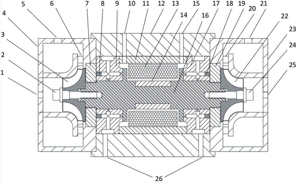
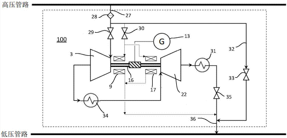
The invention discloses pressure energy recycling equipment and a pipeline pressure energy recycling system. The pressure energy recycling equipment comprises a main shaft extended in the longitudinaldirection, a first expander assembly, a second expander assembly and a power generation assembly. The first expander assembly is provided with a first air inlet and a first air outlet, the second expander assembly is provided with a second air inlet and a second air outlet, the second air inlet can be connected with the first air outlet, the first expander assembly and the second expander assembly can drive the main shaft to rotate, and the power generation assembly is arranged on the main shaft. In the axial direction of the main shaft, a first bearing with which the main shaft is sleeved isarranged between the power generation assembly and the first expander assembly, and a second bearing with which the main shaft is sleeved is arranged between the power generation assembly and the second expander assembly. Pressure loss in pipeline pressure energy recycling can be reduced through the pressure energy recycling equipment and the pipeline pressure energy recycling system.

Description

technical field [0001] The invention relates to the field of pipeline pressure energy recovery, in particular to a pressure energy recovery equipment and a pipeline pressure energy recovery system. Background technique [0002] In order to improve the efficiency of natural gas pipeline transportation, the natural gas in the national natural gas pipeline network always maintains a high pressure during the pipeline transportation process. The pressure is generally around 10MPa, which is much higher than the pressure of 0.4MPa for urban residents. There is huge pressure energy between the main line and the low-pressure natural gas branch line, and the traditional pressure regulating valve device cannot realize energy recovery, resulting in a lot of waste. Using the expander to cooperate with the power generation system to convert the pressure energy into electric energy, recycling this part of the pressure energy can not only produce significant economic benefits, but also elim...

Claims


Application Information

Patent Timeline
Patent Type & Authority Applications(China)
IPC IPC(8): F01K27/00F01K25/08F01D15/10
CPCF01D15/10F01K25/08F01K27/00
Inventor 刘强
Owner 北京大臻科技有限公司
Learn More