Plug-in type three-way normally-closed hydraulic-control reducing valve

A cartridge-type, pressure-reducing valve technology, applied in the field of hydraulic control valves, can solve the problems of simple and fast control of pressure-reducing valves and high manufacturing costs, and achieve compact structure, improved safety, and high pressure regulation range Effect

Pending Publication Date: 2018-04-06
武光玉
View PDF5 Cites 0 Cited by
  • Summary
  • Abstract
  • Description
  • Claims
  • Application Information

AI Technical Summary

Problems solved by technology

However, the manufacturing cost of this method is relatively high, especially for large flow hydraulic systems
[0006] When a pump station drives multiple loads, and a single load needs to be completely reduced to zero pressure without affecting other loads, it is difficult for conventional pressure reducing valves to achieve simple and fast control, such as multi-channel aircraft fatigue test benches, various Dynamic hydraulic testing machine, static hydraulic testing equipment, etc.

Method used


Image

  • Plug-in type three-way normally-closed hydraulic-control reducing valve
  • Plug-in type three-way normally-closed hydraulic-control reducing valve
  • Plug-in type three-way normally-closed hydraulic-control reducing valve

Examples


Embodiment Construction

[0020] The present invention will be described in further detail below in conjunction with the accompanying drawings and examples of specific implementation, but the embodiments should not be interpreted in a limiting manner, and the detailed description of the non-limiting embodiments done in conjunction with the accompanying drawings can make the The technical features, purpose and advantages of the invention will become more obvious.

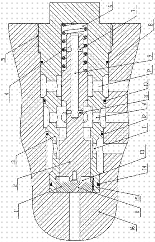
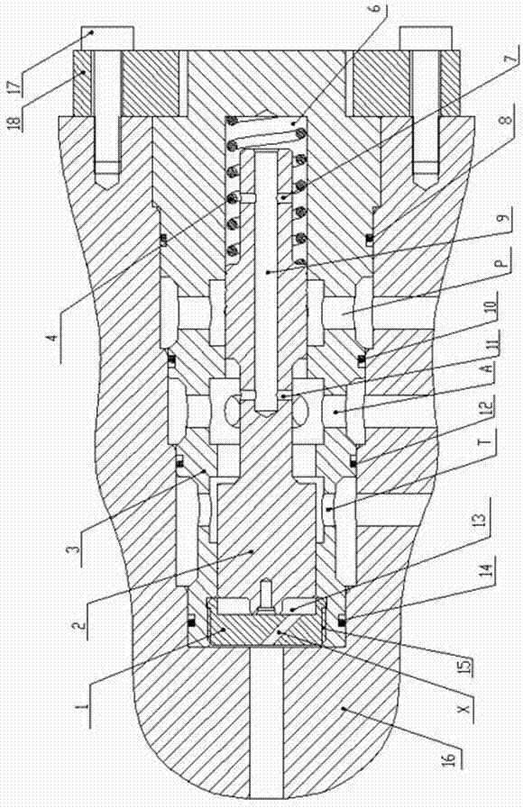
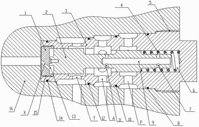
[0021] figure 1 Shown is a schematic structural view of the valve body 3 being installed on the external device 16 in a threaded form, from figure 1 It can be seen from the figure that the present invention contains three working windows of retaining ring 1, spool 2, valve body 3, spring 4, inlet P, outlet A, oil return port T and a window for control---control port X , the outlet A is located between the inlet P and the oil return port T, the valve core 2, the retaining ring 1 and the valve body 3 form the control chamber 13, the control ch...


PUM


Abstract

The invention discloses a plug-in type three-way normally-closed hydraulic-control reducing valve which is characterized by comprising a retainer ring (1), a valve core (2), a valve body (3), a spring(4), three operating windows and a window control port X for control, wherein the three operating windows comprise an inlet P, an outlet A and a return opening T; the outlet is positioned between theinlet and the return opening; a control chamber (13) is formed among the valve core, the retainer ring and the valve body; the control chamber is communicated with the control port; a spring chamber(6) is formed between the valve core and the valve body; n communicated inner holes are formed in the valve core; the inner holes are communicated with an outlet; the spring chamber is communicated with the inner holes; the valve core is in matched with the valve body by virtue of a minimum clearance; the diameter dimension of a matching surface of the valve core and the control chamber is largerthan the diameter dimension of a matching surface of the valve core and the spring chamber; a spring is arranged in the spring chamber; the retainer ring, the inlet, the outlet and the return openingare formed in the valve body; and the control port is formed in the retainer ring. According to the reducing valve disclosed by the invention, a zero pressure state of the outlet can be realized, other branches are not influenced when one pump station drives multiple loads and a single branch is in a completely zero pressure state.

Description

technical field [0001] The invention relates to a hydraulic control valve, in particular to a plug-in three-normally closed hydraulic control pressure reducing valve. Background technique [0002] The hydraulic valve designed according to the principle of "series decompression pressure negative feedback" is called a pressure relief valve. The pressure relief valve is used to control the branch pressure of the hydraulic system so that the output pressure is lower than the system pressure. The pressure reducing valves in the prior art are divided into direct-acting type and control type. The control oil of the control type pressure reducing valve can be supplied from the inside of the pressure reducing valve or from the outside of the pressure reducing valve. [0003] At present, domestic and foreign pressure reducing valves are mainly two-way pressure reducing valves, which are normally open valves. On the premise that the system pressure remains unchanged, the outlet pressur...

Claims


Application Information

Patent Timeline
Patent Type & Authority Applications(China)
IPC IPC(8): F16K17/04F16K11/065
CPCF16K11/0655F16K17/0473
Inventor 武光玉
Owner 武光玉
Why Eureka
Try Eureka