Flange connection device

A connecting device and flange technology, which is applied to flange connections, pipes/pipe joints/fittings, passing components, etc., can solve the problems of collapse, low efficiency of single pipeline fluid delivery, etc., and achieve stable and reliable connections and wide application range Extensive, guarantee the effect of pressure bearing capacity and safety performance

Pending Publication Date: 2018-04-06
YANTAI JEREH PETROLEUM EQUIP & TECH
View PDF0 Cites 82 Cited by
  • Summary
  • Abstract
  • Description
  • Claims
  • Application Information

AI Technical Summary

Problems solved by technology

Existing devices of this kind are all threaded connections, which are easy to break off from the threaded connection, posing a great safety hazard, and limited by the siz

Method used


Image

  • Flange connection device
  • Flange connection device

Examples


Example Embodiment

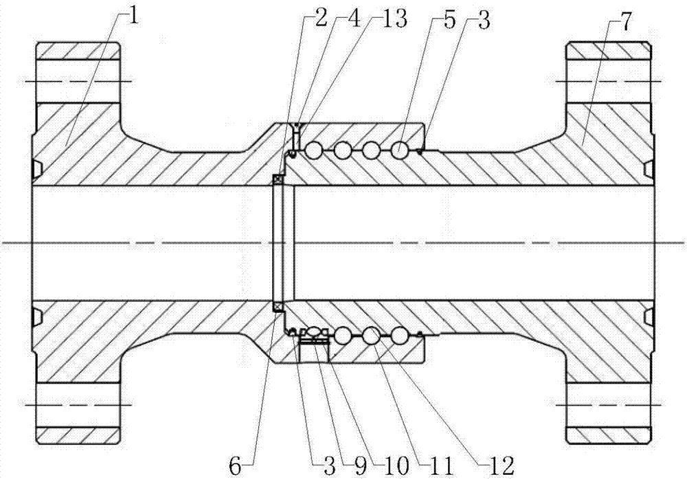
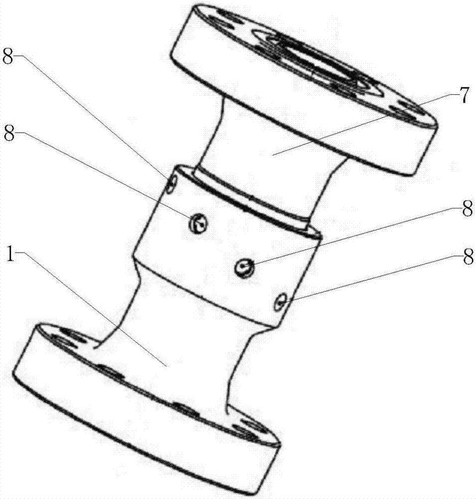
[0031] Example: as attached Figure 1-2 As shown, a flange connection device includes a first joint 1 and a second joint 7. The first joint 1 and the second joint 7 are connected, and a roll is provided between the first joint 1 and the second joint 7 In the device, the first joint 1 and the second joint 7 can freely rotate 360 ​​degrees around the central axis. The first joint 1 and the second joint 7 can be selected in a variety of forms, either direct or elbow joints. Both the first joint 1 and the second joint 7 may be provided with connecting flanges, which pass through corresponding Bolts and other devices are connected to each other.

[0032] The second joint 7 is sleeved in the first joint 1, the inner cavity of the first joint 1 and the inner cavity of the second joint 7 are connected to each other, and the rolling device is connected to the first joint 1 and the second joint 7. connection.

[0033] The rolling device includes a first groove 11 and a second groove 12, t...


PUM


Abstract

The invention provides a flange connection device, comprising a first joint and a second joint, the first joint is connected to the second joint, a rolling device is arranged between the first joint and the second joint, and the first joint is connected to the second joint. The first joint and the second joint can freely rotate 360 ​​degrees around the central axis. The invention can make the connected joints rotate flexibly and conveniently, and avoid the risks of slipping, cracking and tube body cracking caused by excessive inner cavity pressure, excessive local force, and rotation stagnation.

Description

technical field [0001] The invention relates to the field of construction operations related to oil and gas fields, in particular to a flange connection device. Background technique [0002] A flange connection device involved in this patent is used in conjunction with fracturing vehicles, straight pipelines, cock valves, etc., and is mainly used to transport high-pressure fluids such as fracturing fluids, and cooperate with tees to change the direction of pipeline arrangement to complete oil and gas field production increase. Construction work. Existing devices of this kind are all threaded connections, which are easy to break off from the threaded connection, posing a great safety hazard, and limited by the size of the threaded structure, the overall diameter of the manifold cannot be designed too large, and a single pipe The efficiency of transporting fluid through the road is low. Contents of the invention [0003] The purpose of the present invention is to overcome ...

Claims


Application Information

Patent Timeline
IPC IPC(8): F16L23/032F16L23/024F16L23/18
CPCF16L23/024F16L23/032F16L23/18
Inventor 黄金领张树林王坤李建福王新明李帅任光辉
Owner YANTAI JEREH PETROLEUM EQUIP & TECH
Why Eureka
Try Eureka