Flue gas dust removal device

A dust removal device and flue gas technology, which is applied in the direction of combined devices, dispersed particle separation, chemical instruments and methods, etc., can solve the problems of manual cleaning, troublesome operation, and reduced adsorption capacity of filter elements.

Inactive Publication Date: 2018-04-10
ZUNYI CITY GUI KE TECH
View PDF5 Cites 9 Cited by
  • Summary
  • Abstract
  • Description
  • Claims
  • Application Information

AI Technical Summary

Problems solved by technology

However, as the filter element absorbs more and more dust, the dust adsorbed on the filter element becomes thicker and thicker, and the adsorption capacity of the filter element decreas

Method used


Image

  • Flue gas dust removal device
  • Flue gas dust removal device
  • Flue gas dust removal device

Examples


Example Embodiment

[0015] The following is a further detailed description through specific implementations:

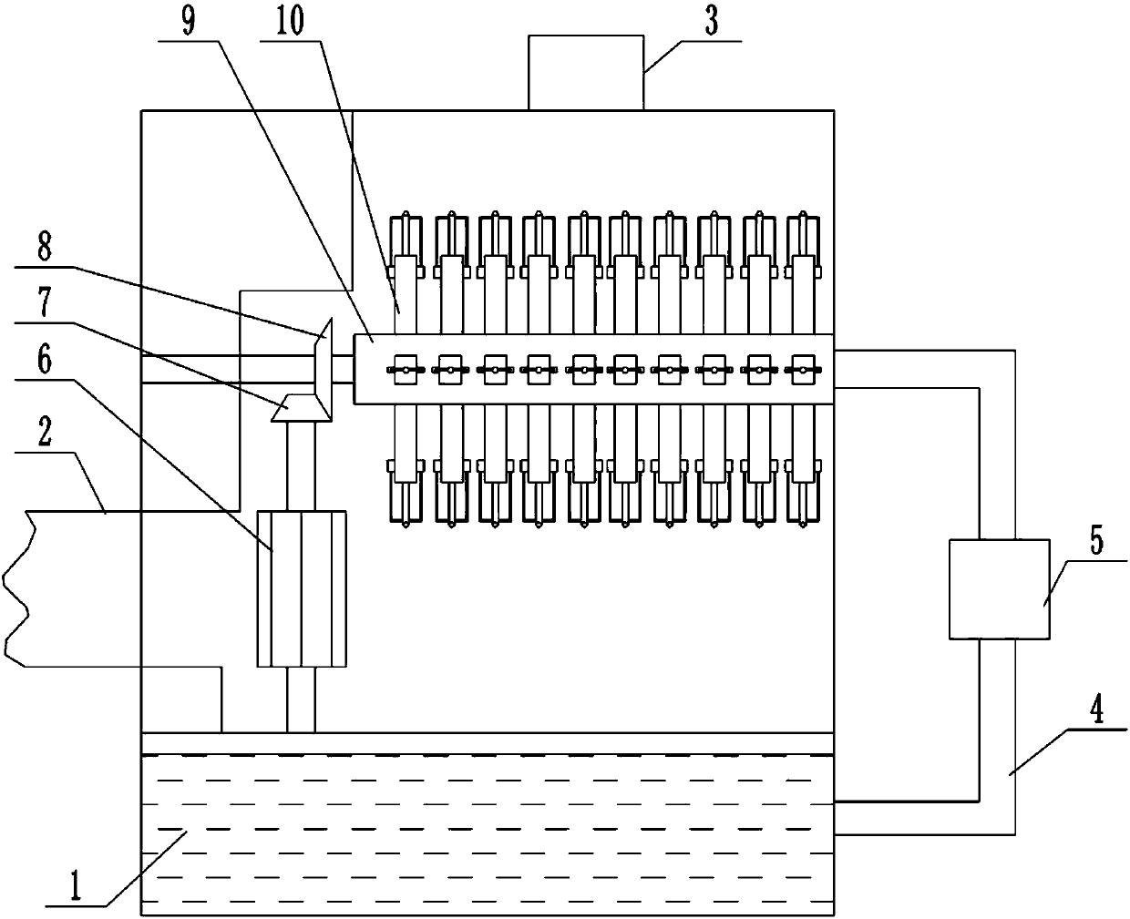
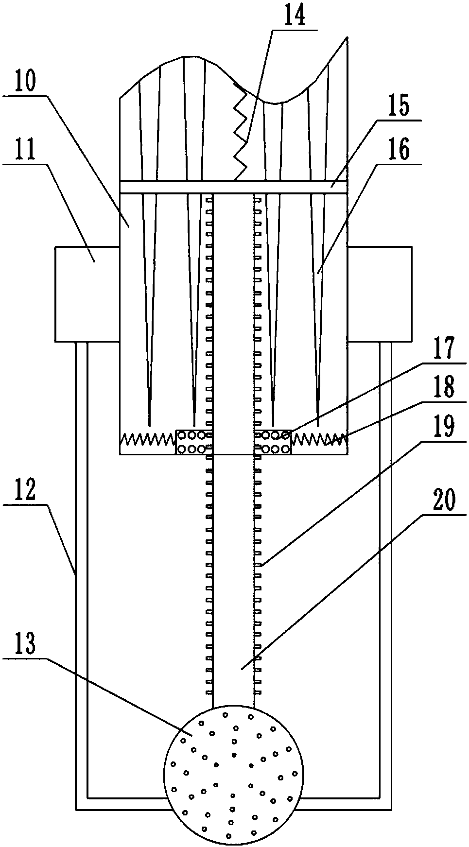
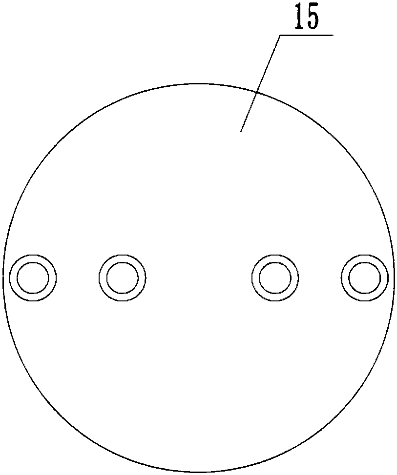
[0016] The reference signs in the drawings of the specification include: water tank 1, air inlet pipe 2, air outlet pipe 3, connecting pipe 4, water pump 5, wind wheel 6, first bevel gear 7, second bevel gear 8, rotating part 9, blade 10 , Cleaning block 11, connecting rod 12, water ball 13, tension spring 14, baffle 15, vertical rod 16, pressure block 17, spring 18, pressure valve 19, water pipe 20.

[0017] The embodiment is basically as attached Figure 1-Figure 3 Shown: a flue gas dust removal device includes a housing, a filter element is arranged above the housing, the filter element includes a rotating part 9 and a blade 10, the rotating part 9 is provided with a first cavity, and the blade 10 is provided with a second cavity Cavity, the blade 10 is provided with an opening communicating with the second cavity, and the first cavity is communicated with the second cavity. A number of ...


PUM


Abstract

The invention relates to a flue gas dust removal device comprising a casing and a filter element. The filter element comprises a rotating part and a blade, a first cavity is arranged in the rotating part, a second cavity is arranged in the blade, the blade is provided with an opening, the rotating part is in communication with the blade, a conical vertical rod connected with the rotating part is arranged in the second cavity, a baffle is slidably arranged on the inner wall of the second cavity, a tension spring is connected between the baffle and the rotating part, the baffle is provided witha through hole, a water pipe is connected with the baffle, the water pipe extends through the opening to the outside of the blade, a pressure valve is arranged on the side wall of the water pipe, andthe water pipe is connected with an internal hollow water ball. The water ball has a water outlet hole, a cleaning block is slidably arranged on the outer wall of the blade, a connecting rod is connected between the cleaning block and the water ball, a pressure block is slidably arranged on the inner wall of the opening, a spring is connected between the inner wall of the blade and the pressure block, a wind wheel is arranged in the casing, the wind wheel drives the rotating part to rotate, the bottom of the casing is provided with a water tank, and the rotating part is communicated with the water tank by a connecting pipe. Th e flue gas dust removal device realizes the automatic cleaning of the filter element.

Description

technical field [0001] The invention relates to the technical field of environmental protection, in particular to a flue gas dedusting device. Background technique [0002] In metallurgy, machinery, chemical industry, building materials and other production industries and in the process of energy conversion such as boilers and kilns, a huge amount of dusty gas is often produced and needs to be treated for environmental protection dust removal. The current dust removal method is mainly based on bag dust removal. The bag filter contains a filter element. After the gas with dust passes through the filter element, the filter element filters the gas, so that the dust adheres to the filter element to achieve the purpose of filtration. However, as the filter element absorbs more and more dust, the dust adsorbed on the filter element becomes thicker and thicker, and the adsorption capacity of the filter element decreases, thereby reducing the dust removal effect. In order to improv...

Claims


Application Information

Patent Timeline
IPC IPC(8): B01D50/00
CPCB01D50/10
Inventor 韩克余张朝友赵明伦袁志勇
Owner ZUNYI CITY GUI KE TECH
Why Eureka
Try Eureka