
Sorting machine system with automatic identifying function and large sorting scope

An automatic identification and sorting machine technology, applied in sorting and other directions, can solve the problems of limited working range and high cost of industrial robots, and achieve the effects of fast movement, enlarged sorting range and convenient maintenance

Inactive Publication Date: 2018-04-10
CHENGDU KECHUANGGU TECH CO LTD
View PDF1 Cites 7 Cited by
  • Summary
  • Abstract
  • Description
  • Claims
  • Application Information

AI Technical Summary

Problems solved by technology

[0005] The purpose of the present invention is to solve the above problems by providing a sorting machine system with automatic identification and a large sorting range, so as to solve the problems of high cost and limited working range of industrial robots in the existing sorting system

Method used


Image

  • Sorting machine system with automatic identifying function and large sorting scope
  • Sorting machine system with automatic identifying function and large sorting scope
  • Sorting machine system with automatic identifying function and large sorting scope

Examples


Embodiment 1

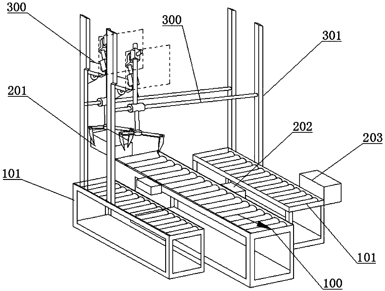
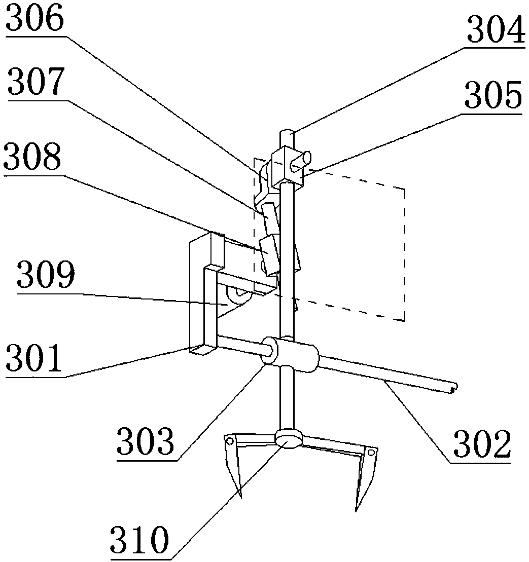
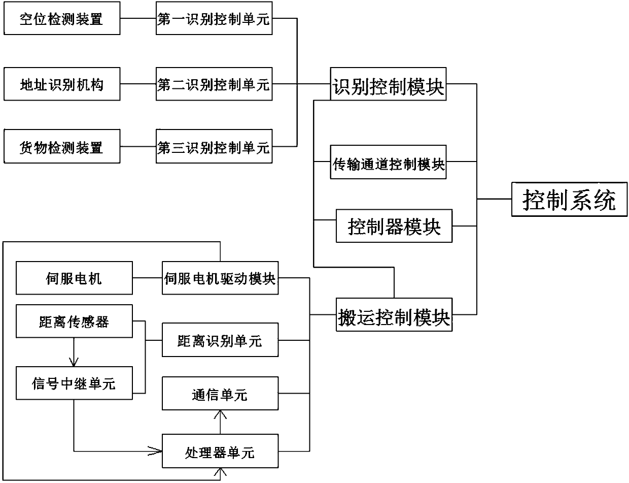
[0040] A sorter system with automatic identification and a large sorting range, including a transmission channel 100, the transmission channel 100 is provided with an identification mechanism 200, a handling mechanism 300 along the product conveying direction, and a control system, the transmission channel 100, and the identification mechanism 200 1. The transfer mechanism 300 is electrically connected with the control system, and the transfer channel 100 is also connected with the sorting channel 101. The transfer mechanism 300 includes a frame 301 arranged on the transfer channel 100, and the frame 301 is provided with a transfer assembly. The track shaft 302 on the frame, the track shaft 302 is sleeved with a sliding base 303, the sliding base 303 is connected with a mechanical claw assembly 310, the sliding base 303 is provided with a connecting rod 304, and the connecting rod 304 is sleeved with a middle slide block 305, the middle slider 305 is hinged with a joint 306, th...

Embodiment 2

[0043] Based on the first embodiment, a linear bearing is provided between the sliding base 303 and the track axis 302 .

[0044] In this embodiment, a linear bearing is provided between the sliding base 303 and the track axis 302, so that the sliding base 303 moves on the track axis 302 more quickly and smoothly, and the product moves more smoothly.

Embodiment 3

[0046] On the basis of the first embodiment, the two ends of the track axis 302 are sleeved with buffer pads.

[0047] In this embodiment, the two ends of the track axis 302 are provided with buffer pads. When the sliding base 303 is sorted in place, the buffer pad absorbs the kinetic energy of the sliding base 303, reduces the movement speed of the sliding base 303, and prevents the sliding base 303 from damaging the frame. 301, also avoid the product falling off under severe vibration when in place.


PUM


Abstract

The invention discloses a sorting machine system with automatic identification and a large sorting range, which belongs to the technical field of sorting and solves the problems of high robot cost and limited sorting range in the existing sorting system. It includes a transmission channel. The transmission channel is equipped with an identification mechanism, a handling mechanism, and a control system. The transmission channel, the identification mechanism, and the handling mechanism are all electrically connected to the control system. The transmission channel is also connected to a sorting channel. The frame on the transmission channel is provided with a handling component. The handling component includes a track axis set on the frame. A sliding base is set on the track axis. A mechanical claw component is connected to the sliding base. Rod, the middle slider is set on the connecting rod, the middle slider is hinged with a joint, the joint is fixedly connected to the rotation rod, the rotation slider is set on the rotation rod, the servo motor is set on the frame, and the output shaft of the servo motor is fixed to the rotation slider. connect. The invention is used for product sorting.

Description

technical field [0001] The invention belongs to the technical field of sorting, and in particular relates to a sorting machine system. Background technique [0002] With the rapid development of the current social economy, all walks of life are constantly accelerating the speed of development, and people's quality of life and living standards are also constantly improving. Both people's life and work have gradually realized modernization and intelligence. The same is true for the logistics and transportation industry. [0003] At present, when most logistics companies are sorting goods, most of them transport the goods to the designated location through unmanned trolleys. At the scene, we can see that there are many trolleys transporting different items in different cities and the workshop is full. Running, the whole process is very chaotic, and many current transportation systems still need to manually load the goods, the workload is very large, and it needs a lot of manpo...

Claims


Application Information

Patent Timeline
IPC IPC(8): B07C3/00B07C3/06B07C3/02B07C3/18
CPCB07C3/00B07C3/02B07C3/06B07C3/18
Inventor 孙元伟
Owner CHENGDU KECHUANGGU TECH CO LTD
Learn More