Engine cylinder head combination fixture processing jig and application method thereof
An engine cylinder and combined fixture technology, applied in the direction of drilling dies for workpieces, etc., can solve the problems of large size error of machining holes, low production efficiency, skew, etc., achieve precise clamping, improve production quality and production efficiency , Use the effect of saving labor
- Summary
- Abstract
- Description
- Claims
- Application Information
AI Technical Summary
Problems solved by technology
Method used
Image
Examples
Embodiment 1
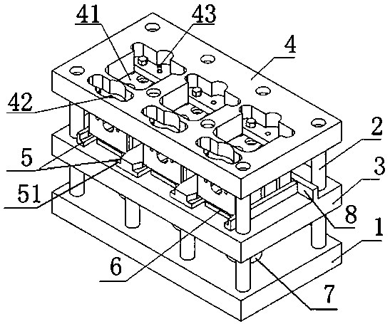
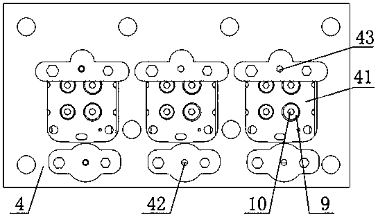
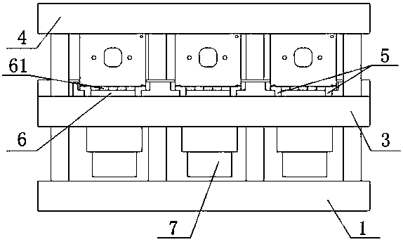
[0012] Embodiment 1: with reference to attached Figure 1-Figure 4 . A kind of engine cylinder head combined fixture processing mold, comprises base 1, described base 1 upper end is provided with middle formwork 3 and upper formwork 4 through multi-column columns 2 and upper formwork 4 is positioned at the top of middle formwork 3; The end face is longitudinally provided with multiple groups of guiding double sliders 5 and a hydraulic lifting tray 6 is arranged between each group of guiding double sliders 5 (that is, a hydraulic lifting tray is provided between the two L-shaped slide rails 51 in the guiding double sliders 5 6); the upper surface of the base 1 is provided with a plurality of hydraulic lifting platforms 7 and each hydraulic lifting platform 7 is located directly below the corresponding hydraulic lifting tray 6, and the lifting rod of the hydraulic lifting platform 7 lifts after passing through the middle template 3 The upper end surface of the rod is fixedly co...
Embodiment 2
[0014] Embodiment 2: on the basis of embodiment 1. A method for using a mold for processing an engine cylinder head combination fixture. When in use, firstly, a plurality of engine cylinder heads to be processed are respectively loaded into corresponding clamping chambers through a plurality of guiding double sliders 5; In the main positioning pin hole 42 and the lower end of the positioning pin is inserted into the pin shaft hole of the corresponding engine cylinder head once the positioning pin passes through the main positioning pin hole 42, so as to realize the positioning before the engine cylinder head clamping; start the hydraulic lift table 7 afterwards to make the hydraulic lift The tray 6 drives the engine cylinder head up together until the upper end surface of the engine cylinder head and the lower end surface of the upper template 4 are in face-to-face contact to realize the clamping of multiple engine cylinder heads; the cylinder head seat ring holes are made on t...
PUM
 Abstract
Description
Claims
Application Information
 - R&D
- Intellectual Property
- Life Sciences
- Materials
- Tech Scout
- Unparalleled Data Quality
- Higher Quality Content
- 60% Fewer Hallucinations
Browse by: Latest US Patents, China's latest patents, Technical Efficacy Thesaurus, Application Domain, Technology Topic, Popular Technical Reports.
© 2025 PatSnap. All rights reserved.Legal|Privacy policy|Modern Slavery Act Transparency Statement|Sitemap|About US| Contact US: help@patsnap.com


