A sand dehydration collection device for engineering construction

A collection device and technology for construction, which is applied in the field of sand and stone dehydration collection devices for engineering construction, can solve the problems of mixing, large manpower consumption, poor quality, etc., and achieve the effect of convenient operation, less manpower consumption, and consistent particle size

Active Publication Date: 2020-05-19
GUANGZHOU PANYU POLYTECHNIC
View PDF9 Cites 1 Cited by
  • Summary
  • Abstract
  • Description
  • Claims
  • Application Information

AI Technical Summary

Problems solved by technology

[0002] Most of the pouring sand and stone used in engineering buildings are collected in the river quarry. Due to the different sizes of sand and stone, it is necessary to sort sand and stone of appropriate size to adapt to the use of engineering buildings. Most of the existing sand and stone sorting and collection devices use The vibrating screen sorts out the required sand and gravel through a screen with a suitable mesh. Although the efficiency of the screen sorting sand and gravel is high, the particle size of the sorted sand and gravel is still uneven. And mixed with a lot of soil, the quality is poor, especially like the fine sand used in engineering construction to paint walls. The sand and gravel sorted out in this way cannot be used directly in engineering construction. The purchased sand and gravel need to be further sorted before being used. The use increases the construction cost. At the same time, the use of the existing sand and gravel screening device consumes a lot of manpower and high labor cost. Facing the rapid development of the engineering and construction industry, the traditional screening device is no longer suitable for the needs of industry development.

Method used


Image

  • A sand dehydration collection device for engineering construction
  • A sand dehydration collection device for engineering construction
  • A sand dehydration collection device for engineering construction

Examples


Embodiment 1

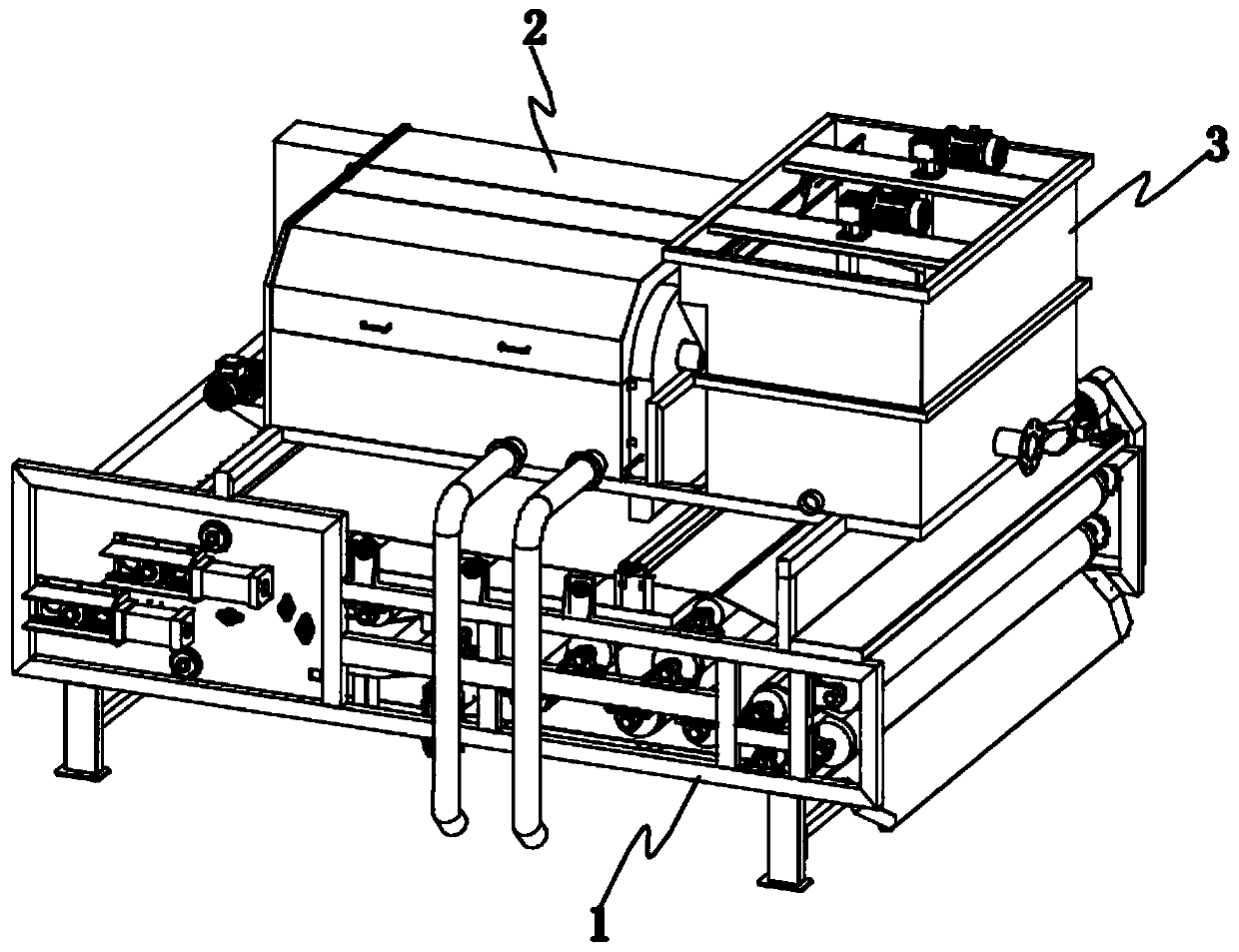
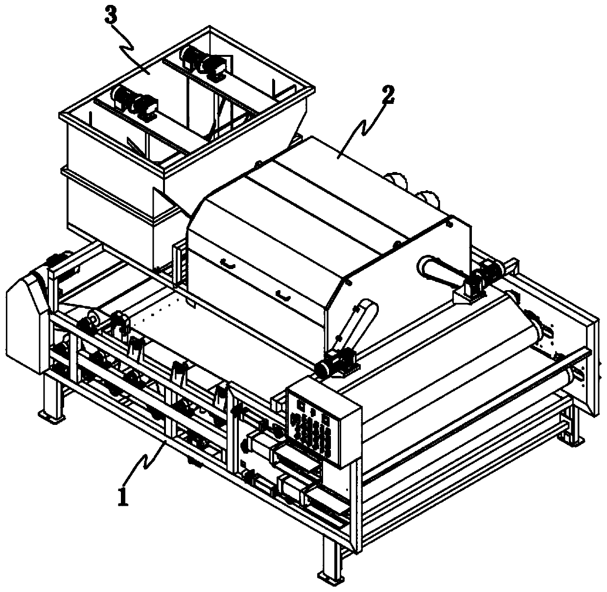
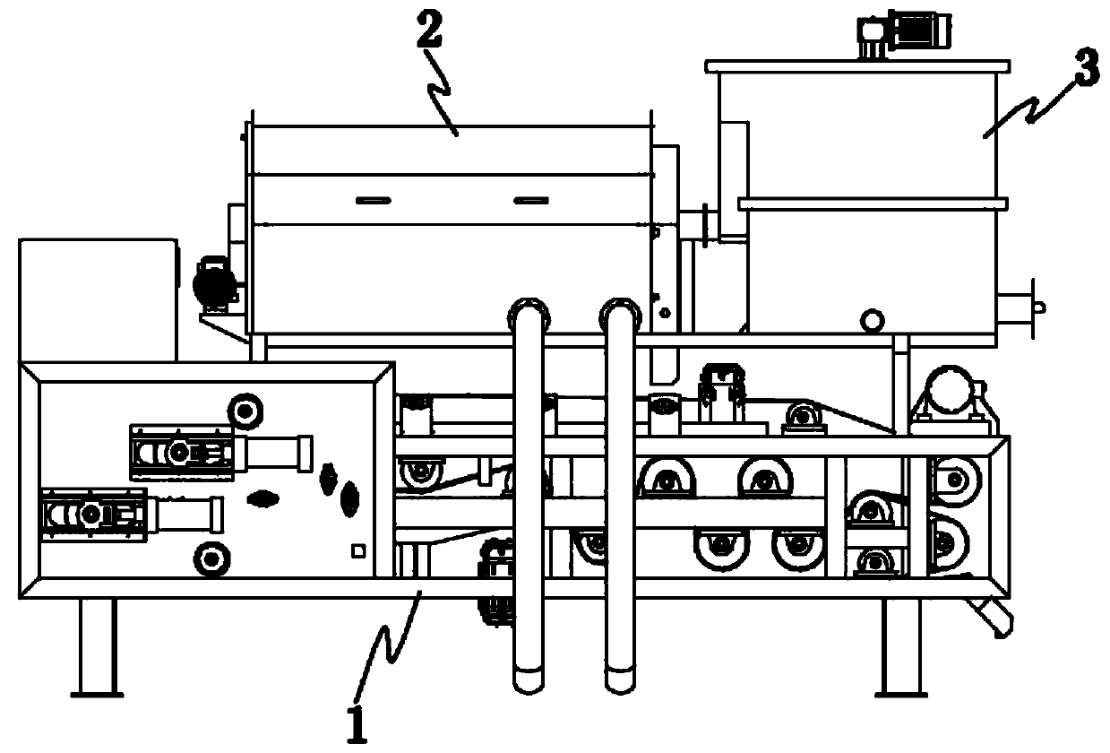
[0035] The stirring input mechanism 3 of this device first inputs the river water mixed with sand and mud debris through the input nozzle 305. After the river water enters the stirring box 301, the stirring motor 303 is started, and the stirring shaft 304 pairs in the stirring box 301 are driven by the stirring motor 303. The river water is stirred, and catalyst is added to the auxiliary input pipe 306 on the side pipe wall of the input nozzle 305 at the same time, which can accelerate the accumulation and sedimentation of large particles in the river water in the stirring box 301. After fully stirring, manually turn the screw nut 310 to adjust the flow rate The adjustment plate 311 moves along the transverse slot 309, thereby opening the output nozzle 308, and adjusting the size of the output nozzle 308, so that the river water flows into the filter collection mechanism 2 along the mixing input pipe 202 connected to the output nozzle 308 to remove fine sand. Filtrate, and simu...

Embodiment 2

[0037] The mixing material input pipe 202 in the filter collection mechanism 2 is connected in the filter framework cylinder 206, and the river water is input into the filter framework cylinder 206 along the material mixing input pipe 202, wherein the filter screen 216 on the surface of the filter framework cylinder 206 filters out the Fine sand, wherein the filter skeleton cylinder 206 is driven and rotated by the filter driving motor 209 on the rear end surface of the chassis body 201, so as to realize the comprehensive filtration of the river water by the filtration skeleton cylinder 206, and the filtering effect is good. Discharge, and discharge to the filter cloth 103 on the dehydration output base 1 along the drain port 210 between the drain cover 203 and the outer surface of the front end of the cabinet body 201, wherein an adjustment plate 211 is set in the drain port 210, which can be manually adjusted The operating rod 212 rotates the adjustment plate 211 to adjust th...

Embodiment 3

[0039] The rotating roller 102 in the dehydration output base 1 of the device is driven to rotate by the conveying motor 105 at the side end, thereby driving the filter cloth 103 wound on the rotating roller 102 to move, and the river water flowing out from the drain 210 falls on the filter cloth 103 , the filter cloth 103 can filter out the silt in the river water, wherein the rotating roller 102 is arranged in parallel with two rows up and down in the dehydration output base 1, to realize the upper and lower layers of river water filtration, the silt filter is fully and thoroughly, and the filtered river water rotates from the lower layer The filter cloth 103 on the roller 102 drips and flows out, and the sludge on the filter cloth 103 moves forward with the rotation of the rotating roller 102, and finally is discharged from the output guide plate 107 on the side end of the dehydration output base 1, wherein the bottom frame is fixed The tension adjustment cylinder 104 connec...


PUM


Abstract

The invention relates to a sand stone dehydration collection device for engineering buildings, wherein the sand stone dehydration collection device includes a dehydration output base and a stirring input mechanism arranged on the dehydration output base; the dehydration output base is also provided with a filter collection mechanism connected with the stirring input mechanism, and the filter collection mechanism comprises a machine box body erected on the upper part of the filter output base. The sand stone dehydration collection device can quickly collect fine sand in rivers; the collected fine sand particles have same size and good quality, and can be used directly in the engineering buildings. At the same time, the device clean silt in the rivers while collecting the fine sand, and hasthe cleaning and environmental-protection functions; and the device is convenient to operate and use and has less human input.

Description

technical field [0001] The invention relates to the technical field of processing equipment for engineering construction materials, in particular to a sand dehydration collection device for engineering construction. Background technique [0002] Most of the pouring sand and stone used in engineering buildings are collected in the river quarry. Due to the different sizes of sand and stone, it is necessary to sort sand and stone of appropriate size to adapt to the use of engineering buildings. Most of the existing sand and stone sorting and collection devices use The vibrating screen sorts out the required sand and gravel through a screen with a suitable mesh. Although the efficiency of the screen sorting sand and gravel is high, the particle size of the sorted sand and gravel is still uneven. And mixed with a lot of soil, the quality is poor, especially like the fine sand used in engineering construction to paint walls. The sand and gravel sorted out in this way cannot be use...

Claims


Application Information

Patent Timeline
Patent Type & Authority Patents(China)
IPC IPC(8): C02F11/00B01D36/02
CPCB01D36/02C02F11/00C02F11/121C02F2103/007
Inventor 张雪松叶雯朱艳峰王毅军
Owner GUANGZHOU PANYU POLYTECHNIC
Why Eureka
Try Eureka