Concrete continuous girder cantilever construction load balance adjusting device and method

A construction load and balance adjustment technology, applied in bridges, bridge construction, erection/assembly of bridges, etc., can solve problems such as continuous beams cannot be guaranteed, concrete pouring progress cannot be kept completely synchronized, major safety accidents, etc., to ensure balance and stability performance, security assurance, and the effect of increasing tolerance

Pending Publication Date: 2018-04-10
SINOHYDRO BUREAU 7 CO LTD
View PDF0 Cites 2 Cited by
  • Summary
  • Abstract
  • Description
  • Claims
  • Application Information

AI Technical Summary

Problems solved by technology

In the actual cantilever construction process, in addition to the fact that the concrete pouring progress cannot be kept completely synchronized, there are many reasons for unbalanced loads at both ends of the cantilever, such as: loads generated by crowds during the construction process, loads generated by construction machinery and materials, hanging baskets The unbalanced loads generated by these factors are difficult to quantify accurately, that is to say, how big these unbalanced loads are, and the T structure formed by the 0# block has produced How big is the bending moment, and whether the generated bending moment exceeds the design allowable value? It is difficult for us to make an accurate judgment during the construction process, so it is impossible to guarantee that the continuous beam will always maintain a safe balance state during the cantilever construction process.
If the existence of these factors is ignored, major safety accidents may occur

Method used


Image

  • Concrete continuous girder cantilever construction load balance adjusting device and method
  • Concrete continuous girder cantilever construction load balance adjusting device and method
  • Concrete continuous girder cantilever construction load balance adjusting device and method

Examples


Embodiment Construction

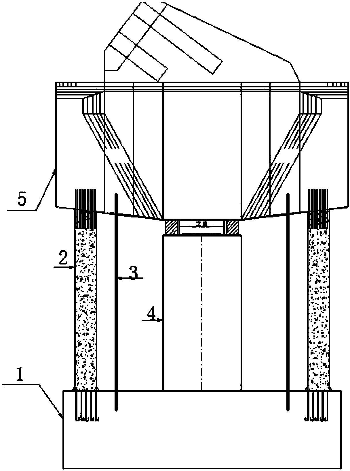
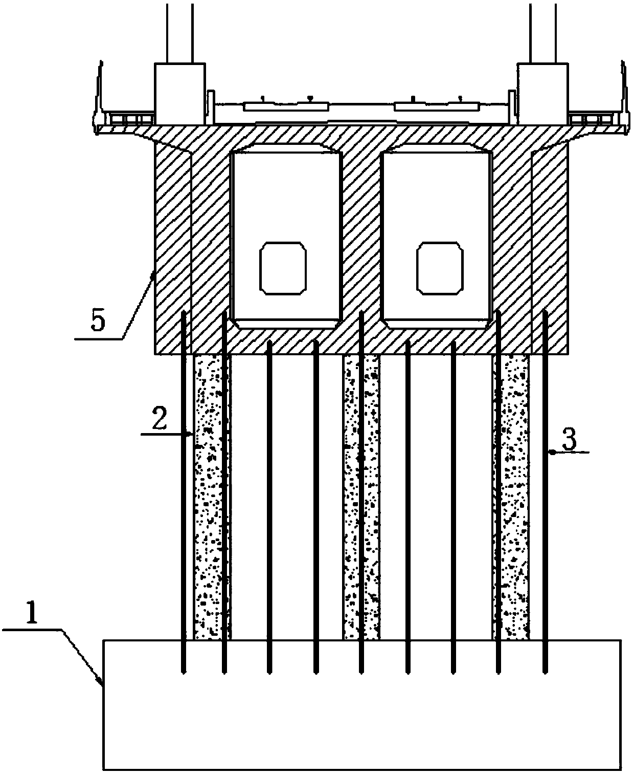
[0023] A load balance adjustment device for concrete continuous beam cantilever construction. Temporary support piers 2 are arranged on the main beam cap 1 on both sides of the main girder pier body 4, and the upper end of the main girder pier body 4 carries the beam body 5. 1 and the beam body 5 are located on both sides of the main beam cap 1 and are buried with finish-rolled rebar 3 .

[0024] The finish-rolled rebars 3 can be connected by extensions.

[0025] 9-12 pieces of finish-rolled rebar 3 are respectively installed on both sides of the main beam cap 1 .

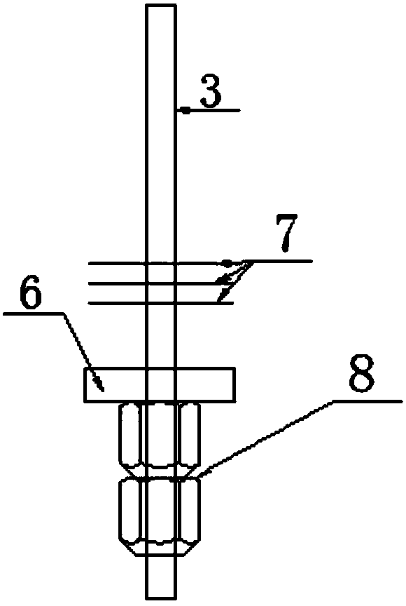
[0026] The finish-rolled rebar 3 is selected from Φ32 finish-rolled rebar.

[0027] The upper and lower ends of the finish-rolled rebar 3 are provided with anchor backing plates 6, the upper end of the embedded beam body is provided with double nuts 8 above the anchor backing plate 6, and three steel mesh sheets 7 are arranged under the anchor backing plate 6; Double nuts 8 are arranged below the anchor backing p...


PUM


Abstract

The invention relates to the field of continuous girder cantilever construction, in particular to a concrete continuous girder cantilever construction load balance adjusting device and method. Temporary buttresses are arranged at the position, located at the two sides of a girder pier body, of a girder bearing platform, the upper end of the girder pier body bears a girder body, and finish rollingsteel bars are embedded at the positions, located at the two sides of the girder bearing platform, between the girder bearing platform and the girder body. The adjusting method includes the steps of pre-embedding the finish rolling steel bars, constructing the continuous girder main girder pier body, setting the temporary buttresses and putting up a temporary support, pouring concrete to completegirder body construction, fixedly connecting the girder body and the girder pier body to form a T-structure form and conducing full-bridge closure. The concrete continuous girder cantilever construction load balance adjusting device and method are provided.

Description

technical field [0001] The invention relates to the field of cantilever construction of continuous beams, in particular to a load balance adjustment device and an adjustment method for cantilever pouring construction of continuous beams of concrete. Background technique [0002] Since the continuous beam cantilever construction method was used by the former West Germany in the 1960s, it has developed into an effective construction method for building large and medium-span bridges. Due to the high technical content of cantilever construction, less investment in equipment and materials, convenient construction, and strong ability to cross unfavorable terrain, it is increasingly used in long-span bridges. The cantilever construction method refers to the construction method of the beam part starting from the pier in the middle of the bridge, gradually extending it in a symmetrical manner, and hanging the beam section until it is closed. The basic procedure of the cantilever pou...

Claims


Application Information

Patent Timeline
IPC IPC(8): E01D21/10
CPCE01D21/105
Inventor 梁学成冉鹏李正全王红力黄强胡勇谢旭智翁斌赵贵朋
Owner SINOHYDRO BUREAU 7 CO LTD
Why Eureka
Try Eureka