Pneumatic Control For A Vacuum Toilet

A vacuum, toilet technology, applied in water supply installations, electrical components, flushing equipment with water tanks, etc., can solve problems such as wrong control, use no longer feasible, and interference of vacuum toilet flushing control.

Inactive Publication Date: 2018-04-10
EVAC GMBH
View PDF2 Cites 18 Cited by
  • Summary
  • Abstract
  • Description
  • Claims
  • Application Information

AI Technical Summary

Problems solved by technology

Both of these can lead to false control
This wrong control either leads to incomplete implementation of the flushing process, leaving the vacuum toilet in an unaccepta

Method used


Image

  • Pneumatic Control For A Vacuum Toilet
  • Pneumatic Control For A Vacuum Toilet
  • Pneumatic Control For A Vacuum Toilet

Examples


Embodiment Construction

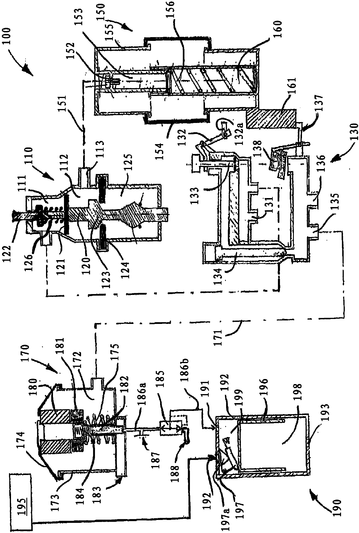
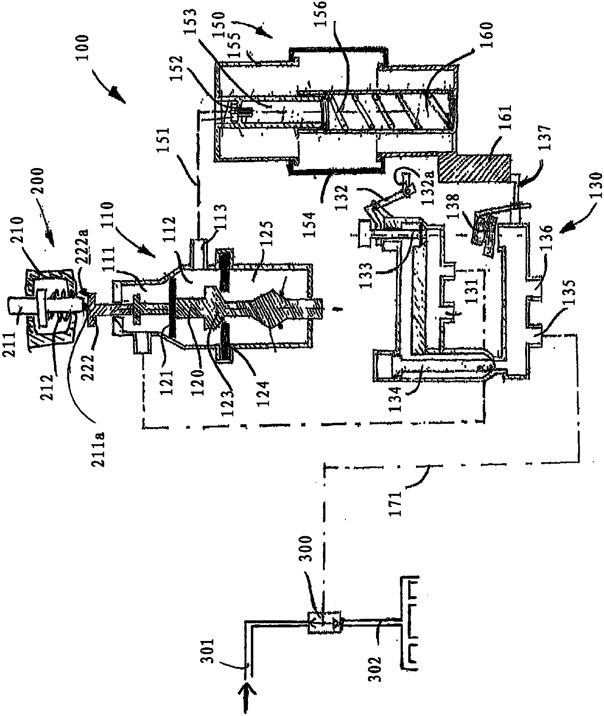
[0055] The drawing shows a control unit 100 comprising an actuating unit 110 , a distribution valve unit 130 and an actuating coupling unit 150 . Furthermore, the flushing control device 170 is a component of the illustrated embodiment of the control device according to the invention. The flushing control device 170 controls the flushing water unit 190 .

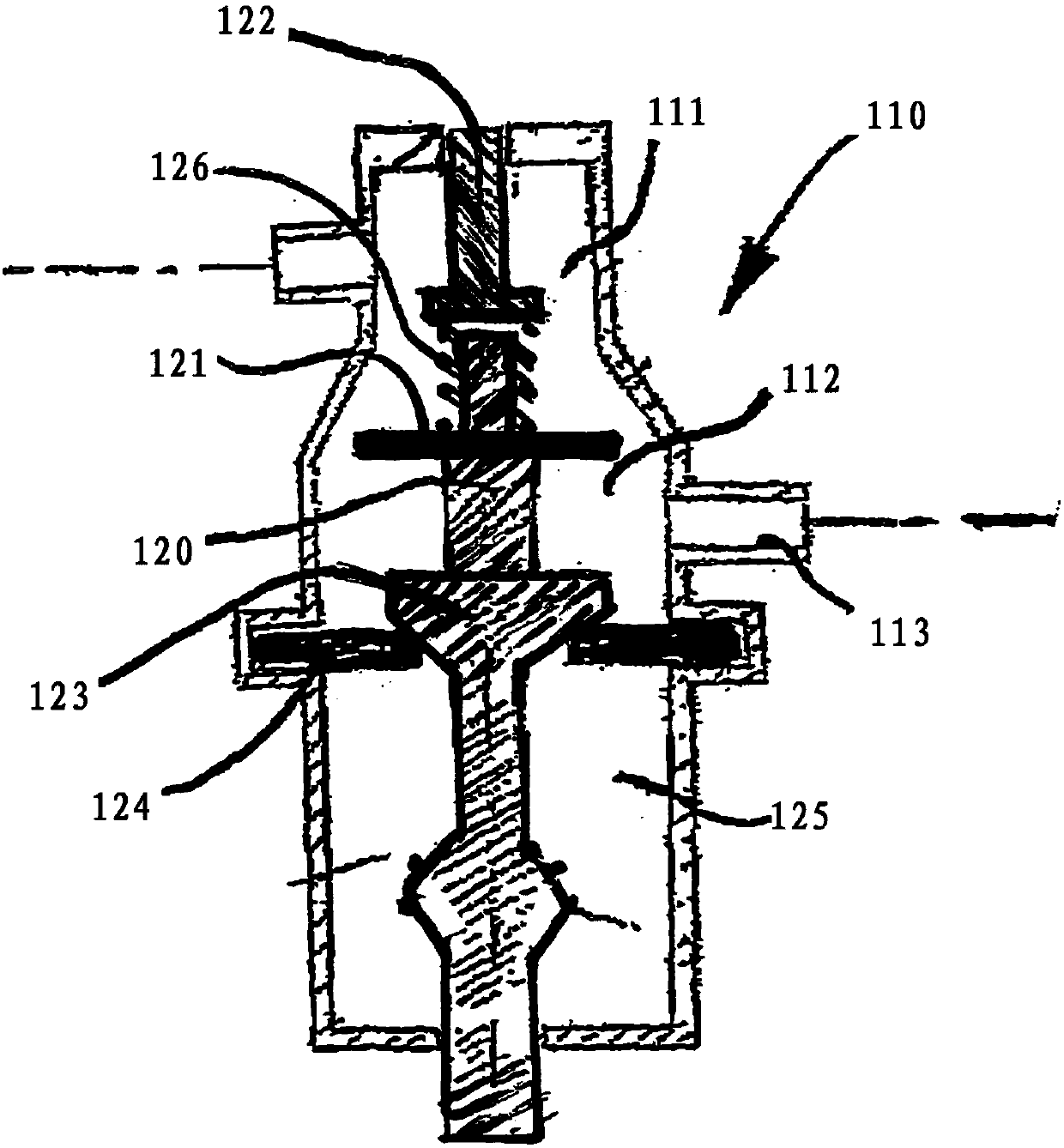
[0056] The power supply of the control device according to the invention takes place via a vacuum connection 131 at the distribution valve unit 130 . The vacuum connection 131 is permanently connected to the negative pressure chamber 111 of the operating unit 110 via the distribution valve unit. The vacuum chamber 111 is sealed from the intermediate chamber 112 of the actuating unit by a sealing element 121 which is arranged on the plunger 120 .

[0057] The punch carries at its upper end a button 122 which can be pressed by the user. By actuating this button, the seal between the negative pressure chamber 111 and the int...


PUM


Abstract

The invention relates to a controller for a vacuum toilet, comprising a control unit (100) with an actuating unit with an actuating element to be manually actuated by user. The actuating element has acontact surface (222a) and an actuation surface (211a) of a push-button key (211) opposite the contact surface (222a), said push-button key being spring-loaded in an initial position and being movable out of said initial position into a trigger position by actuating a press button. In the trigger position, the actuation surface (211a) is in contact with the contact surface (222a), and the actuating element is actuated by the push-button key (211).

Description

technical field [0001] The invention relates to a control device for a vacuum toilet comprising a control unit having an operating unit with operating elements to be manually operated by the user, a dispensing valve unit, the dispensing valve The unit has an air interface and a waste water valve control interface and a shut-off valve for interrupting or releasing the connection between the air interface and the waste water valve control interface; and an operating coupling unit that distributes the valve Coupling with the operating element such that in the first position of the actuating coupling unit the air connection of the distribution valve unit is connected via the shut-off valve to the control interface of the waste water valve, and in the second position of the actuating coupling unit via the shut-off valve the dispensing valve is interrupted. Connection between unit and waste valve control interface. Background technique [0002] Control devices of this type of con...

Claims


Application Information

Patent Timeline
IPC IPC(8): E03D5/02E03F1/00H01H13/00
CPCE03D5/024E03F1/006H01H13/00
Inventor 彼得·欧雷梅克马蒂亚斯·奥特岑
Owner EVAC GMBH
Why Eureka
Try Eureka