Multifunctional storage bin

A storage bin and multi-functional technology, which is applied to fruit hanging devices, horticulture, and botanical equipment and methods, can solve the problems of low efficiency, high cost, and inability to realize the diversification of stored grains, so as to save land resources and reduce Construction cost, material saving effect

Pending Publication Date: 2018-04-13
HENAN UNIVERSITY OF TECHNOLOGY
View PDF12 Cites 1 Cited by
  • Summary
  • Abstract
  • Description
  • Claims
  • Application Information

AI Technical Summary

Problems solved by technology

[0007] (1) One warehouse can only store one kind of grain at the same time, and it is impossible to realize the diversification of grain storage; if you want to store multiple grains, you must occupy more land to build multiple grain warehouses
[0008] (2) When taking out the grain in the granary, it is necessary to use manual or grain fetching machine to fetch the grain, which has high cost and low efficiency

Method used


Image

  • Multifunctional storage bin
  • Multifunctional storage bin
  • Multifunctional storage bin

Examples


Embodiment 1

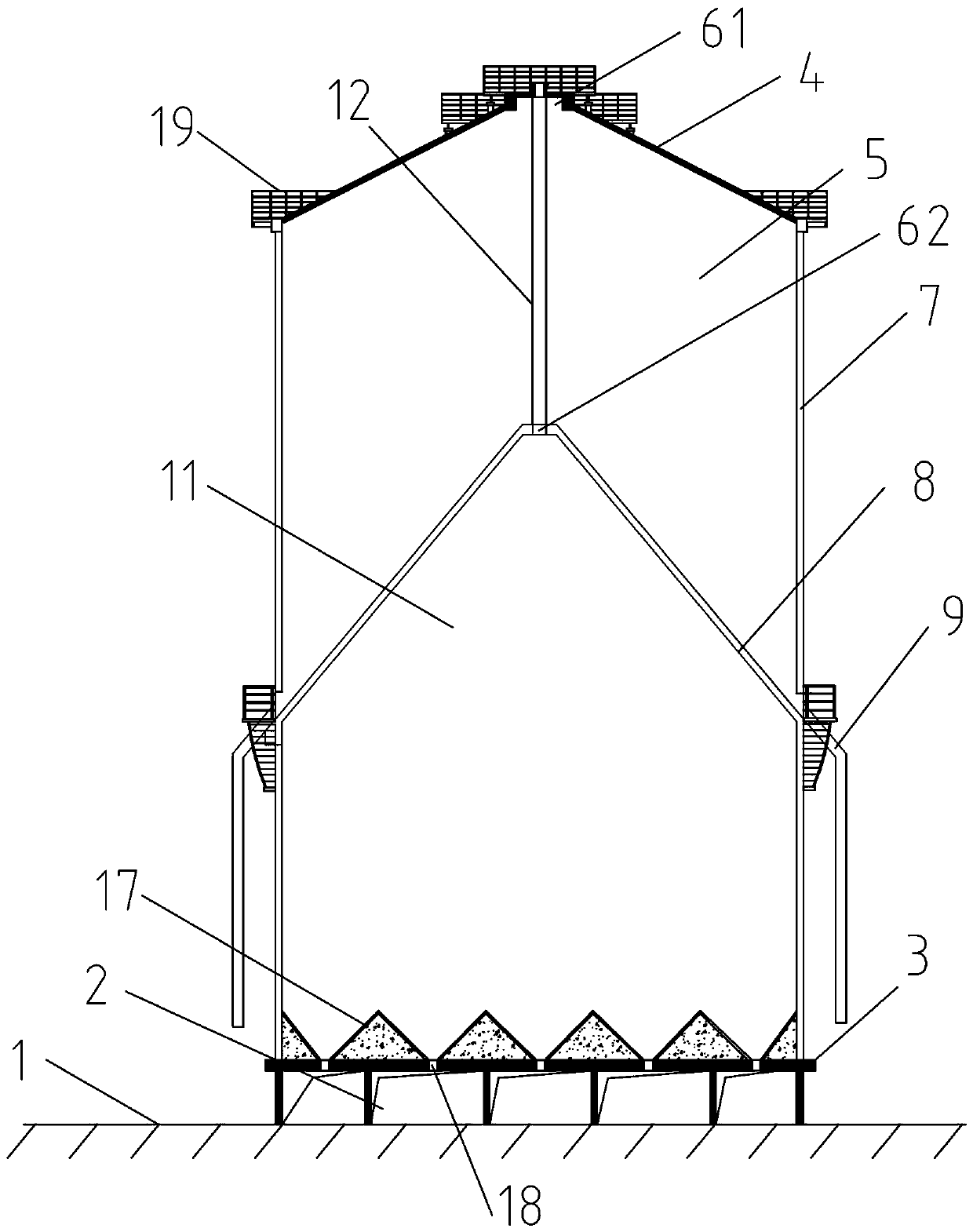
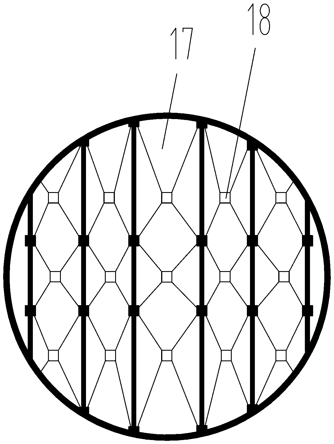
[0047] Such as figure 1 and 2 As shown, the present invention is a columnar structure as a whole, comprising an upper warehouse 5, a lower warehouse 11, a warehouse bottom 3, a warehouse cover 4, a warehouse wall 7, an intermediate spacer 8, and a support member 2; Layer 8 and warehouse wall 7 are enclosed, and the first feeding hole 61 is set on the warehouse cover 4; the lower warehouse 11 is surrounded by the middle interval layer 8, warehouse wall 7, and warehouse bottom 3; the warehouse bottom 3 is above the ground 1 , the support member 2 is used to support the bottom of the warehouse 3; the bottom of the warehouse is provided with a plurality of inverted cone funnels 17 formed by filling slopes, and the lower end of the inverted cone funnels 17 is provided with a discharge hole 18, and the junction of the warehouse wall 7 and the middle interlayer 8 The upper part is provided with an outlet of the upper warehouse, and the outlet of the upper warehouse is provided with ...

Embodiment 2

[0056] The general structure of this embodiment is the same as that of Embodiment 1, the difference is that: Figure 4 As shown, two partitions 20 are set in the upper warehouse 5, the partitions 20 have the same shape and structure as the middle spacer layer 8, and the third feed hole 63 is set at the top of the taper surface of the partition 20. By adding a feed sleeve The pipe realizes the feeding between the first feeding hole 61 and the third feeding hole 63, and the position of the warehouse wall 7 close to the partition 20 is provided with a discharge hole, and the discharge hole is provided with a pipe 21 leading to the ground.

Embodiment 3

[0058] The general structure of this embodiment is the same as that of Embodiment 1, the difference is that: Figure 5 and 6 As shown, the auxiliary warehouse 10 is provided outside the lower warehouse 11. The auxiliary warehouse 10 includes an auxiliary warehouse wall 102, an auxiliary warehouse bottom 101 and an auxiliary warehouse roof 103. The auxiliary warehouse roof 103 is provided with an auxiliary warehouse inlet 104. The bottom of the warehouse 101 is provided with an auxiliary warehouse outlet 105; above the junction of the warehouse wall 7 and the intermediate layer 8, an upper warehouse outlet is arranged, and the upper warehouse outlet and the auxiliary warehouse inlet 104 are connected by a slide pipe 9;

[0059] The outlet of the upper warehouse and the outlet of the auxiliary warehouse are respectively provided with a discharge switch K1 and a discharge switch K2; when the discharge switch is turned on, the material in the corresponding warehouse can flow out. ...


PUM


Abstract

The invention discloses a multifunctional storage bin, and belongs to the technical field of bulk material storage and circulation. The multifunctional storage bin comprises an upper bin (5), a lowerbin (11), a bin bottom (3), a bin cover (4), a bin wall (7), a middle isolation layer (8) and a supporting component (2), and the middle isolation layer (8) is of a conical structure. The upper bin (5) is defined by the bin cover (4), the middle isolation layer (8) and the bin wall (7). The lower bin (11) is defined by the middle isolation layer (8), the bin wall (7) and the bin bottom (3). The bin bottom (3) is arranged above a ground (1), the bin bottom (3) is supported by the supporting component (2), and the bin bottom (3) is provided with a plurality of inverted-cone-shaped funnels and discharging holes. The overground type structure design is adopted in the multifunctional storage bin, the independent feeding and discharging design of the upper bin and the lower bin is adopted, the discharging efficiency of the whole device is improved, and the phenomenon of arching in the outflow process of materials can be prevented.

Description

technical field [0001] The invention belongs to the technical field of bulk material storage and turnover, and in particular relates to a multifunctional storage bin. Background technique [0002] In the process of material turnover and storage, the turnover and storage warehouses affect the efficiency of material turnover; taking grain storage as an example, in order to facilitate the turnover of grain, improve the turnover efficiency, and keep the grain at a high level during the storage process Quality, grain turnover, and the design of storage bins are all the more important. [0003] Chinese patent CN200820190664.9 discloses a grain storage bin, which includes a bin shell with an outlet and a top cover, the top cover is provided with vent holes, and the bin shell, inner tank and ventilation pipe constitute the bin body, The liner is set in the tank shell, and a ventilation interlayer is formed between the periphery and the bottom of the liner and the periphery and bott...

Claims


Application Information

Patent Timeline
Patent Type & Authority Applications(China)
IPC IPC(8): B65D90/10B65D88/64B65D88/06A01F25/14A01F25/18A01F25/20
CPCA01F25/14A01F25/183A01F25/2018B65D88/06B65D88/64B65D90/10
Inventor 王振清张昊梁彩虹宋霞
Owner HENAN UNIVERSITY OF TECHNOLOGY
Why Eureka
Try Eureka