
Automatic lighter gas tank feeding device

An automatic feeding and lighter technology, applied in conveyors, combustion ignition, transportation and packaging, etc., can solve the problems of uneven fuel dosage, difficult maintenance, and increase production costs, so as to improve production efficiency, realize automation, The effect of improving the accuracy of feeding

Inactive Publication Date: 2018-04-13
涟水新邦电子有限公司
View PDF9 Cites 4 Cited by
  • Summary
  • Abstract
  • Description
  • Claims
  • Application Information

AI Technical Summary

Problems solved by technology

[0002] As a small fire-making device, a lighter can be used for smoking, cooking and other fires. It is more convenient in use. In actual production, in order to improve production efficiency, reduce costs and achieve economy, the factory When producing lighters, high-efficiency and automated production methods are often chosen. In the follow-up process of lighter production, the gas tank of the lighter needs to be inflated. The conventional inflation method in the factory is mostly manual inflation, and the inflation efficiency is low. It is easy to grasp, and it is easy to cause uneven fuel dosage. In order to improve production efficiency, the factory will choose automatic feeding machine to inflate the lighter gas tank, but the price of automatic feeding equipment is generally too high, the structure is complicated, and the maintenance is difficult. increased production costs

Method used


Image

  • Automatic lighter gas tank feeding device
  • Automatic lighter gas tank feeding device
  • Automatic lighter gas tank feeding device

Examples


Embodiment Construction

[0014] The following will clearly and completely describe the technical solutions in the embodiments of the present invention with reference to the accompanying drawings in the embodiments of the present invention. Obviously, the described embodiments are only some, not all, embodiments of the present invention. Based on the embodiments of the present invention, all other embodiments obtained by persons of ordinary skill in the art without making creative efforts belong to the protection scope of the present invention.

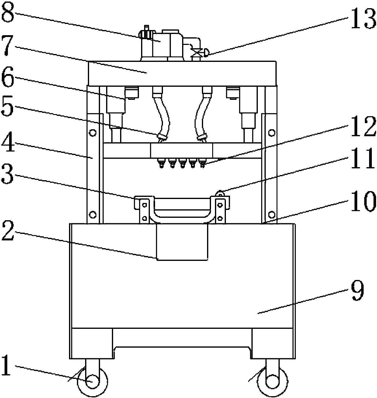
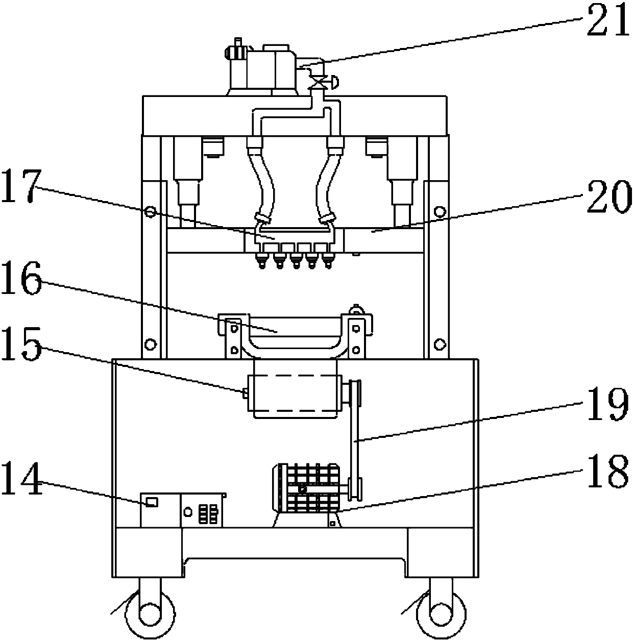
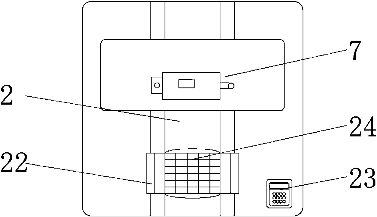
[0015] see Figure 1-3 , an embodiment provided by the present invention: an automatic feeding device for lighter gas tanks, including a first limit chute 3, a bottom box 9 and a support plate 7, and the top of the bottom box 9 is equipped with a first limit chute 3. A mobile tray 22 is installed on the surface of the first limit chute 3, and a placement frame 16 is installed on the surface of the mobile tray 22. The surface of the placement frame 16 is evenly...


PUM


Abstract

The invention discloses an automatic lighter gas tank feeding device, which comprises a first spacing sliding chute, a bottom tank and a support plate. The first spacing sliding chute is formed in thetop part of the bottom tank; a movable tray is arranged on a surface of the first spacing sliding chute; a conveyor belt is arranged on the top part of the bottom tank on the inner side of the firstspacing sliding chute; support columns are arranged on the top part of the bottom tank at two sides of the first spacing sliding chute; the support plate is arranged on the top parts of the support columns; an air charging pump is arranged on the top part of the support plate; anti-explosion hose pipes are arranged on the bottom part of the support plate; an installation plate is arranged on the tail ends of the anti-explosion hose pipes; electromagnetic nozzles are arranged on the bottom part of the installation plate; a control electricity box is arranged in the bottom tank; and a servo motor is arranged in the bottom tank on one side of the control electricity box. According to the automatic lighter gas tank feeding device provided by the invention, through arranging a series of structures, multiple lighter gas tanks can be fed simultaneously by the device during a feeding process, so that the production efficiency and the feeding accuracy are improved, and the device is convenientto use.

Description

technical field [0001] The invention relates to the technical field of production and processing equipment, in particular to an automatic feeding device for lighter gas tanks. Background technique [0002] As a small fire-making device, a lighter can be used for smoking, cooking and other fires. It is more convenient in use. In actual production, in order to improve production efficiency, reduce costs and achieve economy, the factory When producing lighters, high-efficiency and automated production methods are often chosen. In the follow-up process of lighter production, the gas tank of the lighter needs to be inflated. The conventional inflation method in the factory is mostly manual inflation. While the inflation efficiency is low, the amount of inflation is not high. It is easy to grasp, and it is easy to cause uneven fuel dosage. In order to improve production efficiency, the factory will choose automatic feeding machine to inflate the lighter gas tank, but the price of ...

Claims


Application Information

Patent Timeline
Patent Type & Authority Applications(China)
IPC IPC(8): B65G21/10B65G17/00F23Q2/52
Inventor 陈珊
Owner 涟水新邦电子有限公司
Learn More