Al technical title is built by PatSnap Al team. It summarizes the technical point description of the patent document.
A cutter and yarn technology, applied in textiles, papermaking, textile material cutting, etc., can solve problems such as yarn rebound, low production efficiency, troublesome cleaning, etc., to prevent yarn rebound, improve efficiency, and textile The effect of convenient processing
Inactive Publication Date: 2018-04-13
新昌县绿松科技有限公司
View PDF0 Cites 4 Cited by
Summary
Abstract
Description
Claims
Application Information
AI Technical Summary
This helps you quickly interpret patents by identifying the three key elements:
Problems solved by technology
Method used
Benefits of technology
Problems solved by technology
[0002] The original meaning of textile is taken from the general term of spinning and weaving, but with the continuous development and improvement of the textile knowledge system and subject system, especially after the emergence of non-woven textile materials and three-dimensional composite weaving technologies, the current textile is not only a traditional Hand spinning and weaving, including non-woven fabric technology, modern three-dimensional weaving technology, modern electrostatic nano-netting technology and other textiles for clothing, industrial use and decoration, often need to cut the yarn in the textile operation, However, when the current yarn is cut, the cutter will rebound the yarn when cutting the yarn, which will cause the yarn to be messy, and it will be troublesome to clean up later, resulting in low production efficiency.
Method used
Image
Click on the blue label to locate the original text in one second.
Reading with bidirectional positioning of images and text.
Examples
Embodiment Construction
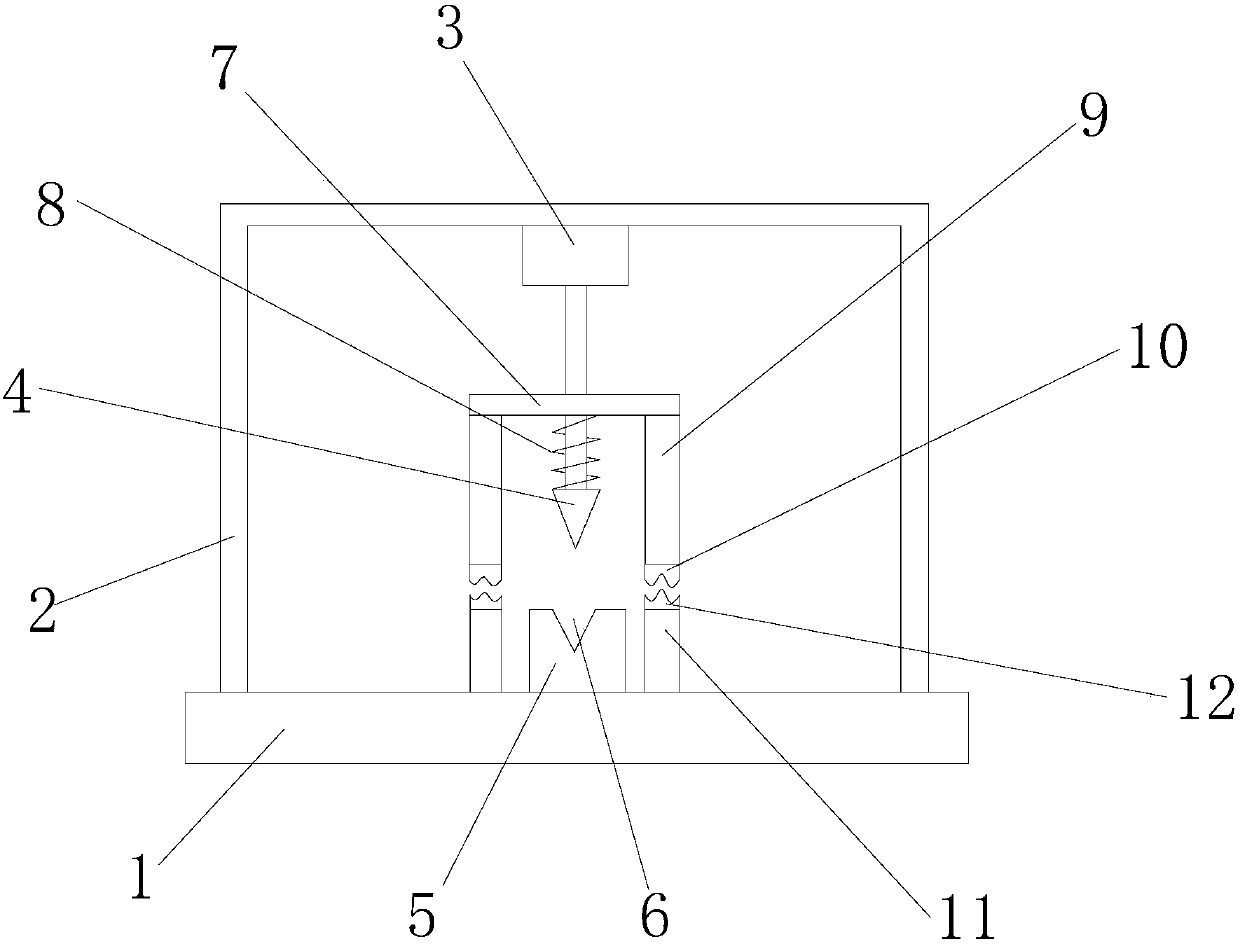
[0012] refer to figure 1 , a yarn cutter of the present invention comprises a base 1, a frame 2, a cylinder 3, a cutter 4, a knife seat 5, a knife groove 6, a mounting rod 7, a spring 8, a wire pressing plate 9, an upper rubber pad 10, Press wire seat 11 and lower rubber pad 12, the top of described base 1 is fixedly provided with frame 2, and the bottom of described frame 2 is fixedly provided with cylinder 3 that output shaft is vertically arranged downwards, and the output of described cylinder 3 The lower end of the shaft is fixed with a cutter 4, and directly below the cutter 4 is provided with a knife seat 5 fixed on the top of the base 1, and the upper surface of the knife seat 5 is provided with a knife groove 6 matched with the cutter 4 The outer side of the output shaft of the cylinder 3 is slidably provided with a horizontally arranged installation rod 7, and a spring 8 is connected between the bottom of the installation rod 7 and the upper part of the cutter 4, and...
PUM
Abstract
The invention discloses a yarn cutter, which comprises a base, a frame, an air cylinder, a cutter, a knife seat, a knife groove, a mounting rod, a spring, a wire pressing plate, an upper rubber pad, a wire pressing seat and a lower rubber pad. The upper part of the base is fixedly equipped with a frame, the lower part of the frame is fixedly equipped with a cylinder, the lower end of the output shaft of the cylinder is fixedly equipped with a cutter, and a knife seat is arranged directly below the cutter, and the knife The upper surface of the seat is provided with a knife groove, and the outer side of the output shaft of the cylinder is slid to be provided with a mounting rod. There is a pressing board, the bottom of the pressing board is provided with an upper rubber pad, and a pressing seat fixed on the upper part of the base is provided directly below the pressing board, and a lower rubber pad is provided on the upper part of the pressing board , Compared with the prior art, the yarn can be cut quickly, the yarn rebound can be effectively prevented, the efficiency of yarn cutting is improved, and the textile processing is brought convenience.
Description
【Technical field】 [0001] The invention relates to the technical field of textile equipment, in particular to a yarn cutter. 【Background technique】 [0002] The original meaning of textile is taken from the general term of spinning and weaving, but with the continuous development and improvement of the textile knowledge system and subject system, especially after the emergence of non-woven textile materials and three-dimensional composite weaving technologies, the current textile is not only a traditional Hand spinning and weaving, including non-woven fabric technology, modern three-dimensional weaving technology, modern electrostatic nano-netting technology and other textiles for clothing, industrial use and decoration, often need to cut the yarn in the textile operation, However, when the current yarn is cut, the cutter will rebound the yarn when cutting the yarn, which will cause the yarn to be messy, and the cleaning in the later stage will be troublesome, resulting in lo...
Claims
Application Information
Patent Timeline
Application Date:The date an application was filed.
Publication Date:The date a patent or application was officially published.
First Publication Date:The earliest publication date of a patent with the same application number.
Issue Date:Publication date of the patent grant document.
PCT Entry Date:The Entry date of PCT National Phase.
Estimated Expiry Date:The statutory expiry date of a patent right according to the Patent Law, and it is the longest term of protection that the patent right can achieve without the termination of the patent right due to other reasons(Term extension factor has been taken into account ).
Invalid Date:Actual expiry date is based on effective date or publication date of legal transaction data of invalid patent.