Eureka AIR delivers breakthrough ideas for toughest innovation challenges, trusted by R&D personnel around the world.

Drainage ditch

A technology for drainage ditches and drainage areas, applied to drainage structures, waterway systems, water supply devices, etc., can solve the problems of lack of drainage ditches, etc., and achieve the effects of saving manpower, easy cleaning, and reducing management costs

Pending Publication Date: 2018-04-13
葳西雨水工程技术(上海)有限公司
View PDF4 Cites 1 Cited by
  • Summary
  • Abstract
  • Description
  • Claims
  • Application Information

AI Technical Summary

Problems solved by technology

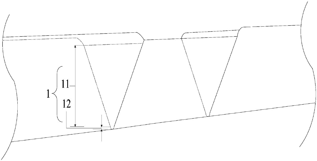
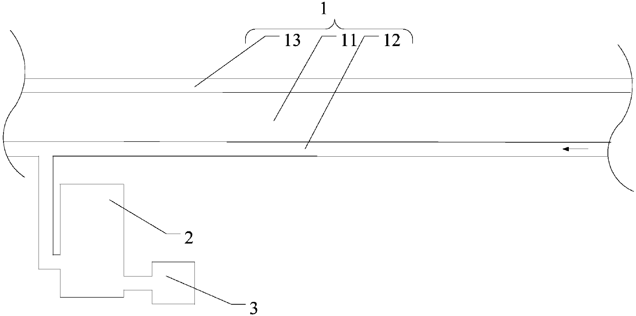
[0007] In view of the above-mentioned shortcomings of the prior art, the purpose of the present invention is to provide a drainage ditch, which is used to solve the problem of the lack of drainage ditch in the prior art that can simultaneously solve the problem of draining, purifying, and preventing stagnation of rainwater

Method used


Image

  • Drainage ditch
  • Drainage ditch
  • Drainage ditch

Examples


Embodiment Construction

[0046] The implementation of the present invention will be illustrated by specific specific examples below, and those skilled in the art can easily understand other advantages and effects of the present invention from the contents disclosed in this specification.

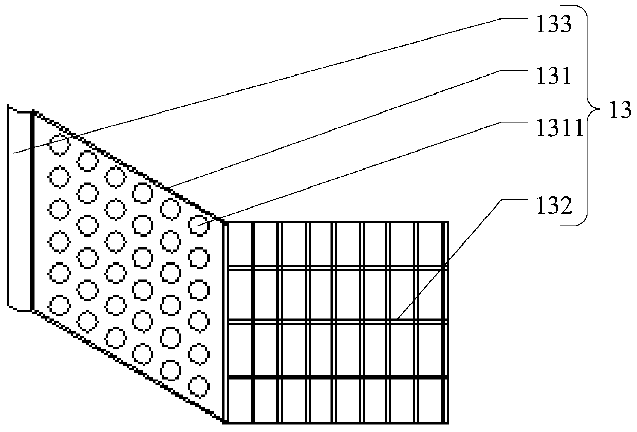
[0047] see Figure 1 to Figure 4 . It should be noted that the structures, proportions, sizes, etc. shown in the drawings attached to this specification are only used to match the content disclosed in the specification, for those who are familiar with this technology to understand and read, and are not used to limit the implementation of the present invention. Limiting conditions, so there is no technical substantive meaning, any modification of structure, change of proportional relationship or adjustment of size, without affecting the effect and purpose of the present invention, should still fall within the scope of the present invention. The disclosed technical content must be within the scope covered. At the sa...


PUM


Abstract

The invention provides a drainage ditch, which includes a first drainage area and a second drainage area connected from top to bottom, the width of the first drainage area gradually decreases from top to bottom, and the top surface of the first drainage area It is open and the top surface is provided with a rainwater grate, the width of the second drainage area gradually decreases from top to bottom, and the second drainage area is provided with a bottom surface. The drainage ditch provided by the present invention ensures that the water volume is sufficient to flow during light rains to carry away sediment and garbage, and the width is sufficient to accommodate a large amount of rainfall during heavy rains so as not to overflow to the outside of the ditch. The gutter can effectively drain, purify, and prevent stagnation of rainwater, is easy to open and clean, has a simple structure, low cost, is easy to clean, and meets the requirements of national regulations.

Description

technical field [0001] The invention belongs to the technical field of drainage facilities, and relates to a drainage ditch. Background technique [0002] In urban construction, the efficiency of pavement drainage facilities and the capacity of underground drainage pipelines directly affect the collection and drainage of urban rainwater. However, in recent years, during the rainy season, the roads in cities all over the country are flooded and even waterlogged. On the one hand, it is due to the limited capacity of existing underground drainage pipes, and on the other hand, it is directly related to the efficiency of road drainage facilities. Reason is mainly relevant with the single structure of existing pavement rainwater grate. At present, in cities, for street drainage, rainwater grates are often simply installed at the rainwater outlets of the sewers on both sides of the street. It will produce a large amount of sewage to pollute the environment, and it is also a breed...

Claims


Application Information

Patent Timeline
Patent Type & Authority Applications(China)
IPC IPC(8): E03F5/04E03F5/06
CPCE03F5/0402E03F5/0404E03F5/06
Inventor 曾誊录
Owner 葳西雨水工程技术(上海)有限公司
Why Eureka
Eureka Blog
Learn More