Engine cooling system

A technology for engine cooling and cooling water, which is applied in the direction of engine cooling, engine components, machines/engines, etc., can solve problems such as poor engine performance, and achieve the effect of improving performance

Inactive Publication Date: 2018-04-13
ANHUI JIANGHUAI AUTOMOBILE GRP CORP LTD
View PDF4 Cites 20 Cited by
  • Summary
  • Abstract
  • Description
  • Claims
  • Application Information

AI Technical Summary

Problems solved by technology

[0004] The purpose of the present invention is to provide an engine cooling s

Method used


Image

  • Engine cooling system
  • Engine cooling system

Examples


Embodiment Construction

[0026] In order to enable those skilled in the art to better understand the technical solution of the present invention, the solution will be further described in detail below in conjunction with specific embodiments.

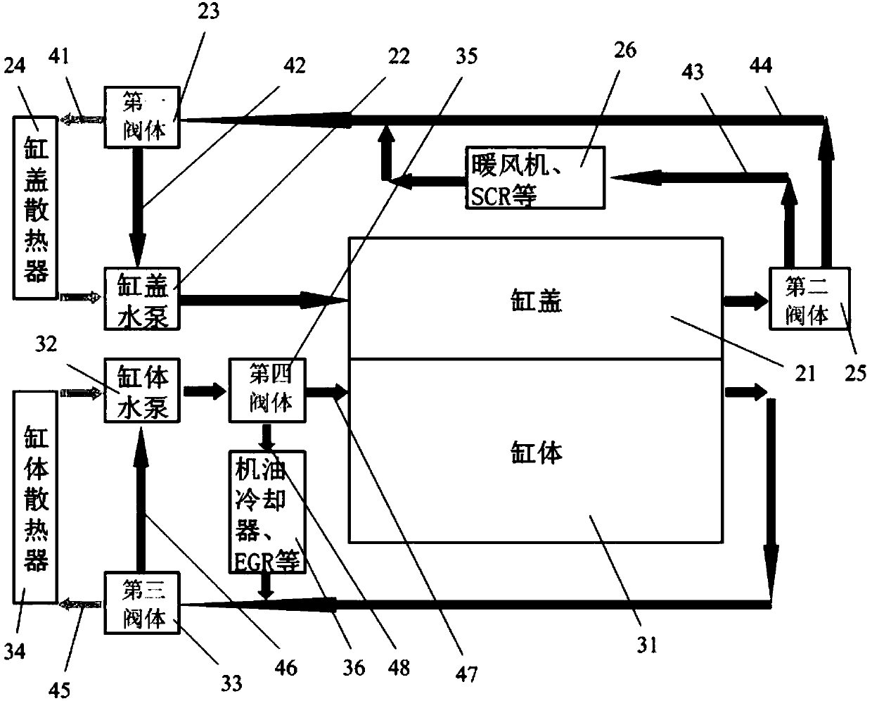
[0027] like figure 2 As shown, the embodiment of the present invention provides an engine cooling system, which includes a cylinder head circulation waterway and a cylinder block circulation waterway that are independent of each other. A cylinder head water pump 22 and a cylinder head 21 are arranged in sequence on the cylinder head circulation waterway, and the cylinder head circulation After the cooling water in the waterway flows out from the outlet of the cylinder head water pump 22, it passes through the cylinder head 21 and is supplied to the inlet of the cylinder head water pump 22; the cylinder body water pump 32 and the cylinder body 31 are sequentially arranged on the cylinder body circulation waterway, and the cylinder body circulation waterway Afte...


PUM


Abstract

The invention provides an engine cooling system. The engine cooling system comprises a cylinder cover circulating waterway and a cylinder body circulating waterway which are mutually independent. Thecylinder cover circulating waterway is provided with a cylinder cover water pump and a cylinder cover in sequence. Cooling water in the cylinder cover circulating waterway flows out from an outlet ofthe cylinder cover water pump, then passes through the cylinder cover and is provided for an inlet of the cylinder cover water pump. The cylinder body circulating waterway is provided with a cylinderbody water pump and a cylinder body in sequence. Cooling water in the cylinder body circulating waterway flows out from an outlet of the cylinder body water pump, then passes through the cylinder bodyand is provided for an inlet of the cylinder body water pump. According to the engine cooling system, the cylinder cover circulating waterway and the cylinder body circulating waterway of the enginecooling system are mutually independent, the cylinder cover and the cylinder body can be cooled correspondingly, and the flowing amount of the cooling water flowing through the cylinder body can further be made to be different from that of the cooling water flowing through the cylinder cover so that the cylinder body and the cylinder cover can be cooled simultaneously to most suitable temperaturescorrespondingly, and the performance of an engine is improved effectively accordingly.

Description

technical field [0001] The invention relates to the technical field of automobile cooling systems, in particular to an engine cooling system. Background technique [0002] The role of the engine cooling system is to ensure that the engine works in a suitable temperature range. Only by ensuring the proper working temperature of the engine can the engine obtain good power, economy and emission performance. With the increasingly stringent national fuel consumption and emission regulations, it is necessary for the cooling system to control the temperature of the engine more precisely. [0003] like figure 1 As shown, it is an existing engine cooling system, and the arrows in the figure indicate the flow direction of cooling water, which generally includes a cylinder block 11, a cylinder head 12, a radiator 14, a common water pump 13, a heater and a selective catalytic reduction system (SelectiveCatalytic Reduction, referred to as SCR) etc. 16, engine oil cooler and exhaust gas...

Claims


Application Information

Patent Timeline
IPC IPC(8): F01P3/02F01P5/10F01P7/16
CPCF01P3/02F01P5/10F01P7/165F01P2003/027F01P2005/105F01P2007/146F01P2050/22
Inventor 杨洪震李昌陈晓东胡志胜郑久林冶金鑫吴鹏范皖元刘吉林王宏大王次安王海宁穆立侠
Owner ANHUI JIANGHUAI AUTOMOBILE GRP CORP LTD
Why Eureka
Try Eureka