Unmanned aerial vehicle precise landing system and method based on infrared beacon and vision

A UAV and infrared technology, applied in the field of UAV flight, can solve the problems of large amount of calculation, large environmental impact, high target angle requirements, and achieve the effect of strong anti-interference ability, strong compatibility and flexible connection

Inactive Publication Date: 2018-04-13
SHENZHEN JTT TECH CO LTD
View PDF13 Cites 12 Cited by
  • Summary
  • Abstract
  • Description
  • Claims
  • Application Information

AI Technical Summary

Problems solved by technology

The automatic landing process only relies on the positioning accuracy of the GNSS system to realize the landing method. Because the GNSS accuracy error level is above one meter, the descent process is easily affected by factors such as wind force and the environment. When the landing accuracy exceeds one meter, it cannot meet the precise landing of the drone. requirements
[0004] At present, there are image recognition methods and FPGAs to realize the precise landing of UAVs, but the two methods cannot realize image interception or splicing, and these two methods have a large amount of calculation, high requirements for target angles, relatively large environmental impact, and dark light Can not be carried out under the environment and other problems

Method used


Image

  • Unmanned aerial vehicle precise landing system and method based on infrared beacon and vision
  • Unmanned aerial vehicle precise landing system and method based on infrared beacon and vision
  • Unmanned aerial vehicle precise landing system and method based on infrared beacon and vision

Examples


Embodiment 1

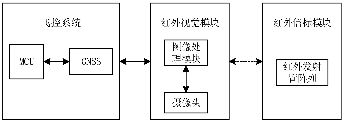
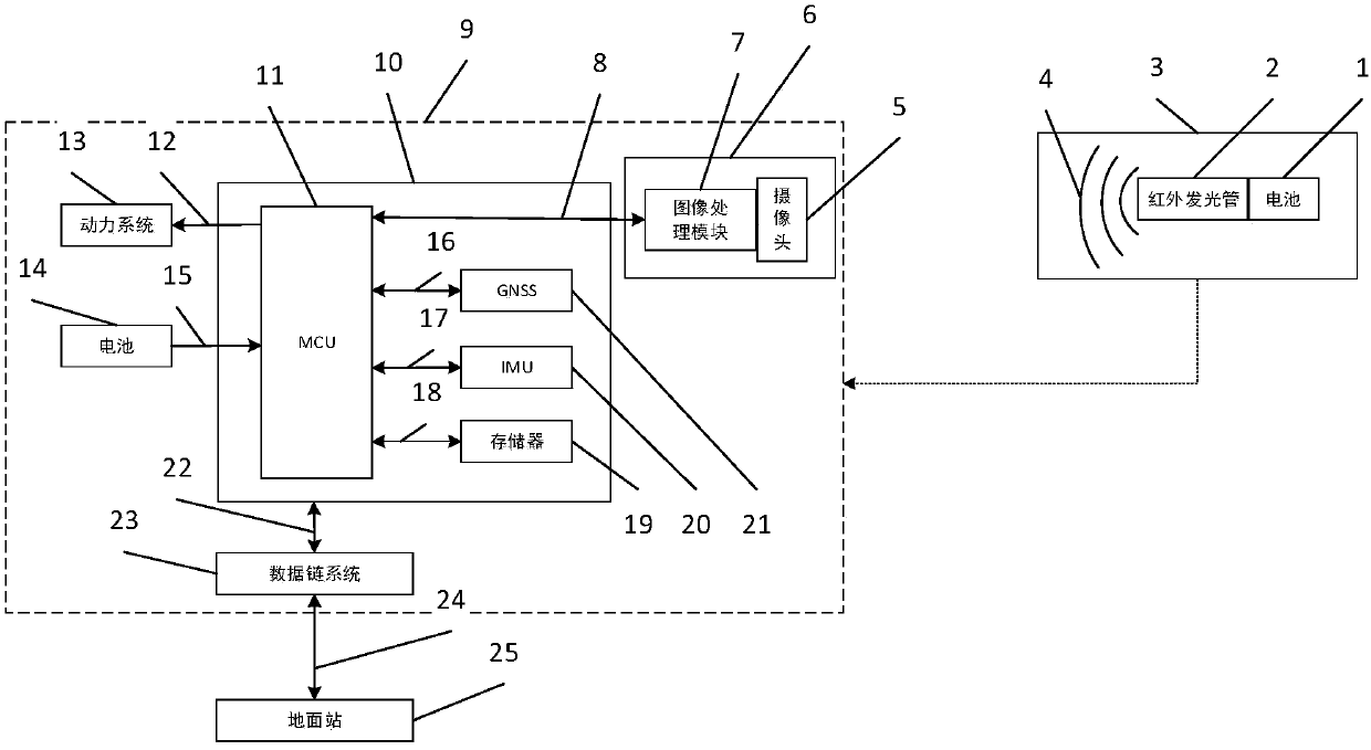
[0067] like figure 1 As shown, an embodiment of the present invention is provided based on an infrared beacon and vision-based UAV precision landing system, which mainly includes an infrared beacon module, a flight control system and an infrared vision module, and a three-axis stabilization system is installed on the UAV. The platform and the flight control system include at least a GNSS positioning module and an MCU, wherein the MCU and the GNSS positioning module are connected through a data interface to obtain the current flight position coordinates of the UAV, so as to cooperate with the flight control system to maintain the stability and stability of the UAV during flight. The orientation remains unchanged; the infrared vision module is installed on the three-axis stabilized gimbal to keep the camera facing vertically downwards, and capture the infrared identification signal (infrared rays) sent by the infrared beacon module to identify the position of the infrared beacon ...

Embodiment 2

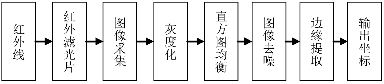
[0090] An embodiment of the present invention provides a precise landing method for UAVs based on infrared beacons and vision. The UAV includes at least an infrared vision module and a flight control system. The flight control system includes at least a GNSS positioning module and an MCU. The vision module includes at least a camera and an image processing module. A three-axis stabilization platform is installed on the UAV, and the camera is installed on the three-axis stabilization platform. The specific steps are as follows:

[0091] Step 1: When the UAV lands, use the GNSS positioning module to estimate whether the current position is above the position of the target landing point;

[0092] Step 2: When the GNSS positioning module estimates that the current position of the UAV is above the position of the target landing point and the height is above 15 meters, the flight control system obtains the estimated position of the target landing point through the GNSS positioning mo...


PUM

PropertyMeasurementUnit
Launch angleaaaaaaaaaa

Abstract

The invention provides an unmanned aerial vehicle precise landing system and method based on infrared beacon and vision. The system mainly comprises an infrared beacon module, a flight control systemand an infrared vision module. A tri-axial stability platform is installed on an unmanned aerial vehicle so as to cooperate with the flight control system to keep the unmanned aerial vehicle to be stable and in different direction in the flight process. The infrared vision module is installed on the tri-axial stability platform so as to keep a camera of the infrared vision module to be verticallydownward always, and capture infrared beacon signals emitted by the infrared beacon module so as to recognize the position of the infrared beacon module in a target landing point. The infrared beaconmodule is set in the position of the target landing point of the unmanned aerial vehicle. When the unmanned aerial vehicle lands, the infrared emission pipe array emits infrared rays to cooperate withthe infrared vision module to carry out data acquisition so as to recognize the position of the infrared beacon module in the target landing point. According to the invention, by combining the infrared vision technology and the target information source recognition technology, precise landing control of the unmanned aerial vehicle can be achieved.

Description

technical field [0001] The present invention relates to the technical field of unmanned aerial vehicles, in particular to a system and method for precise landing of unmanned aerial vehicles based on infrared beacons and vision. Background technique [0002] A drone is an unmanned aircraft that is controlled by a remote control device or an on-board program control device. Because of its wide application, simple structure, excellent cost-effectiveness, no risk of casualties, and good maneuverability, it plays an extremely important role in modern warfare and has broad prospects in the civilian field. [0003] Traditional UAVs generally use the GNSS positioning system (Global Navigation Satellite System), and rely on the positioning accuracy of the GNSS system to achieve landing during the landing process through manual control or automatic landing. This method requires the operator to have strong flight experience, emergency response capability and psychological endurance, a...

Claims


Application Information

Patent Timeline
IPC IPC(8): G05D1/10
CPCG05D1/101
Inventor 李明政
Owner SHENZHEN JTT TECH CO LTD
Why Eureka
Try Eureka