
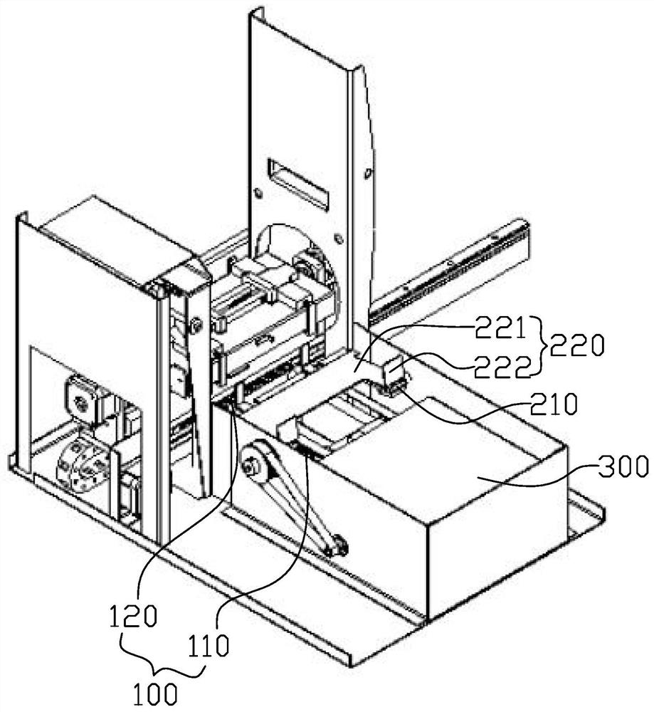
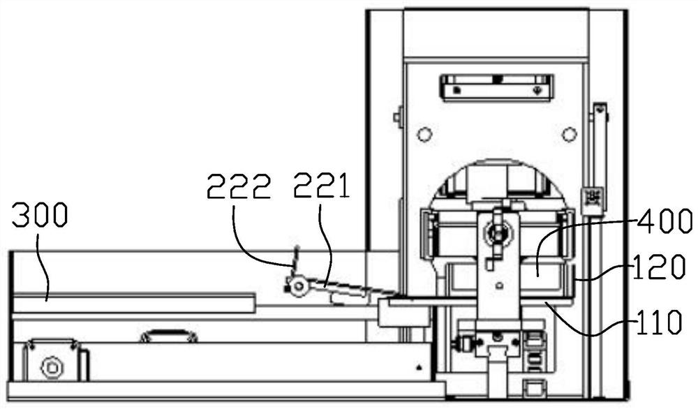
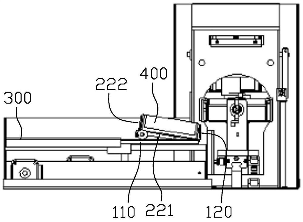
A test tube discharging device and mixing device

A test tube and material-removing plate technology, which is applied in the field of medical and health equipment, can solve the problems such as the inability to realize the adjustment of the test tube row attitude, the scope of application, the limitation of the scene, the complex structure, etc., and achieve the effects of simple structure, saving power source and low cost.

Active Publication Date: 2021-04-16
SONOSCAPE MEDICAL CORP
View PDF5 Cites 0 Cited by
  • Summary
  • Abstract
  • Description
  • Claims
  • Application Information

AI Technical Summary

Problems solved by technology

With the advancement of technology, a large number of detection and analysis tasks are currently completed by automated equipment. Taking blood cell analysis as an example, placing the test tube row with the sample in the relevant equipment can automatically complete the loading, mixing, puncturing, and withdrawal. materials and other steps, most of the material return devices in the prior art are complex in structure, high in cost, and difficult to meet people's needs; at the same time, the existing material return devices can generally only realize the separation of the test tube row and the working position on the equipment, and cannot realize The adjustment of the attitude of the test tube row, so that its scope of application and scenes are limited to a certain extent

Method used


Image

  • A test tube discharging device and mixing device
  • A test tube discharging device and mixing device
  • A test tube discharging device and mixing device

Examples


Embodiment Construction

[0025] The idea, specific structure and technical effects of the present invention will be clearly and completely described below in conjunction with the embodiments and accompanying drawings, so as to fully understand the purpose, scheme and effect of the present invention. It should be noted that, in the case of no conflict, the embodiments in the present application and the features in the embodiments can be combined with each other.

[0026] It should be noted that, unless otherwise specified, when a feature is called "fixed" or "connected" to another feature, it can be directly fixed and connected to another feature, or indirectly fixed and connected to another feature. on a feature. In addition, descriptions such as up, down, left, and right used in the present invention are only relative to the mutual positional relationship of the components of the present invention in the drawings.

[0027] Also, unless defined otherwise, all technical and scientific terms used herei...


PUM


Abstract

The invention relates to the field of medical and health equipment, and discloses a test tube discharging and unloading device and a mixing device, wherein the unloading device includes a driving mechanism and a bearing mechanism; The driving stroke of the plate includes the first stroke of driving the test tube row to move from the first position to the carrying mechanism. The carrying mechanism includes a loading plate, which can be turned around a rotating shaft to adjust the attitude of the test tube row. The driving stroke also includes a second stroke of driving the inverted test tube row to move from the loading plate to the second position. The present invention can adjust the attitude of the test tube row during the process of removing the material of the test tube row through the segmental movement of the stripping plate, and the whole process is carried out automatically without additional strokes, which helps to reduce the time of stripping the material, increase the efficiency, and has a simple structure , low cost, and easy to implement; at the same time, the test tube row is placed vertically after being turned over by the bearing mechanism, which can maximize the use of the space of the buffer platform.

Description

technical field [0001] The invention relates to the field of medical and sanitary instruments, in particular to a material returning / receiving device for a test tube row, and also relates to a mixing device using the material returning device. Background technique [0002] As a common carrier for storing samples, the test tube row is widely used in biochemical research, medical testing and other fields. With the advancement of technology, a large number of detection and analysis tasks are currently completed by automated equipment. Taking blood cell analysis as an example, placing the test tube row with the sample in the relevant equipment can automatically complete the loading, mixing, puncturing, and withdrawal. materials and other steps, most of the material return devices in the prior art are complex in structure, high in cost, and difficult to meet people's needs; at the same time, the existing material return devices can generally only realize the separation of the tes...

Claims


Application Information

Patent Timeline
Patent Type & Authority Patents(China)
IPC IPC(8): B01L3/14B01F15/02
CPCB01L3/502B01F35/71B01F2101/23
Inventor 卢江涛曾光
Owner SONOSCAPE MEDICAL CORP
Learn More