Detachable painting mist ventilating channel

A detachable, paint mist technology, applied in the direction of spraying devices, etc., can solve the problems of time-consuming, cumbersome installation, and difficult cleaning, etc., and achieve the effect of reducing labor intensity, improving production efficiency, and facilitating on-site operation for workers

Inactive Publication Date: 2018-04-17
成都欧喷数控设备有限公司
View PDF6 Cites 0 Cited by
  • Summary
  • Abstract
  • Description
  • Claims
  • Application Information

AI Technical Summary

Problems solved by technology

[0003] The present invention provides a detachable paint mist air passage, which solves the problem that the air passage in the prior art is fixedly installed with the front and rear mechanisms, and there are problems such as difficult cleaning, long time consumption, and cumbersome installation.

Method used


Image

  • Detachable painting mist ventilating channel
  • Detachable painting mist ventilating channel
  • Detachable painting mist ventilating channel

Examples


Embodiment 1

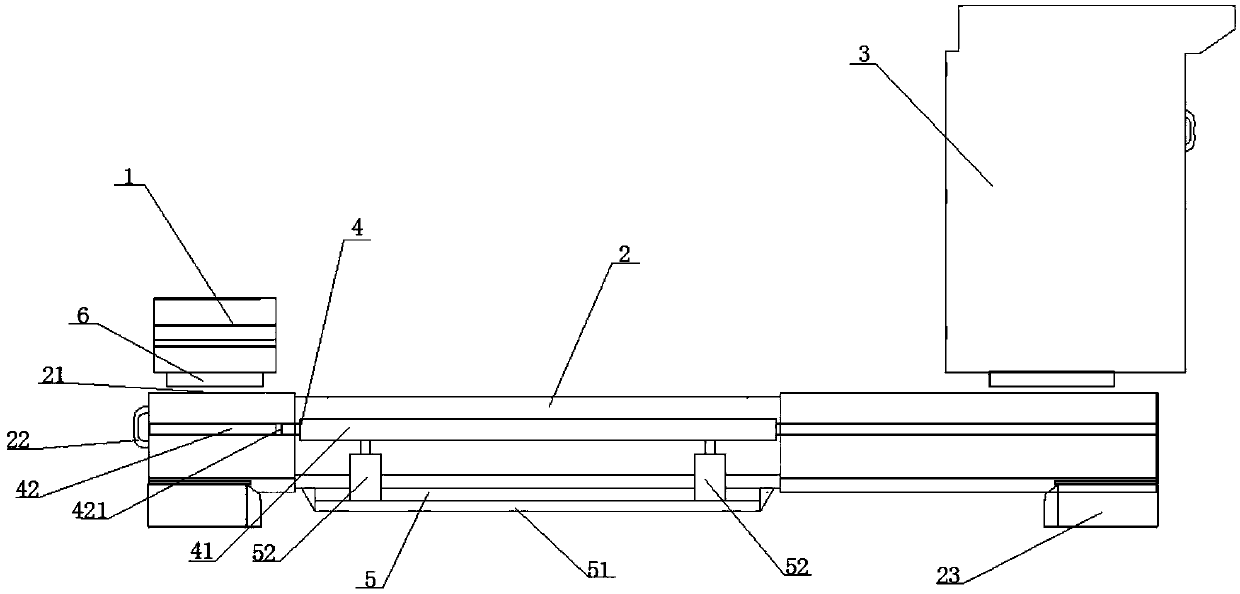
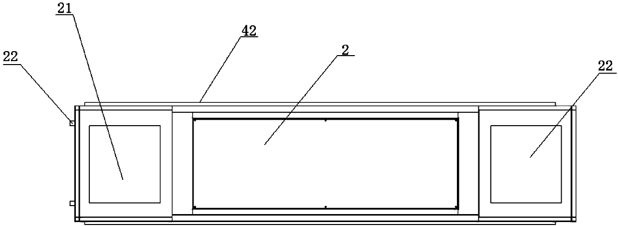
[0029] A detachable paint mist passage, including an air duct 2, one end of which is connected to the air inlet filter system 1 for sucking paint mist away, and the other end of the air duct 2 is connected to discharge paint mist to The exhaust filter system 3 in the air is characterized in that: a front and rear reciprocating device 4 and a vertical lifting device 5 are provided under the air duct 2, and two ends of the air duct 2 are provided for connecting the air duct 2 with the air inlet. The fixed automatic locking device of the filtering system 1 and the exhaust filtering system 3 also includes an intelligent controller, and the front and rear reciprocating device 4 and the vertical lifting device 5 are all electrically connected with the intelligent controller; Through the setting of the front and rear reciprocating motion device 4, the vertical lifting device 5 and the automatic locking device, after the entire passage is installed, it can be realized through external ...

Embodiment 2

[0031] On the basis of Embodiment 1, the vertical lifting device 5 includes a fixed bracket 51, and the fixed bracket 51 is provided with multiple groups of synchronous cylinders 52, and the output shaft of the cylinder 52 is provided with a front and rear reciprocating device 4, In this embodiment, the present invention realizes the vertical lifting of the air duct 2 through the setting of multiple sets of synchronous cylinders 52 and the function of the intelligent controller, so that the air duct 2 is easy to disassemble and achieves the purpose of facilitating on-site operation and cleaning by workers , Improve production efficiency and reduce labor intensity.

Embodiment 3

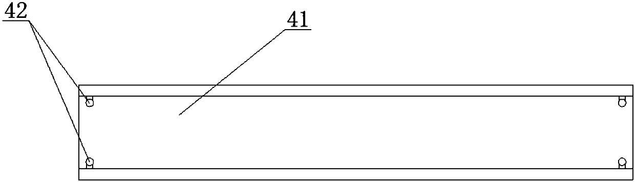
[0033] On the basis of Embodiment 1 or 2, the front and rear reciprocating device includes a chute 41 arranged on the output shaft of the cylinder 52, and a slide rail 42 is provided on the side wall of the air duct 2, and the slide rail 42 is located in the chute 41 and can move forward and backward along the length direction of the chute 41 . In this embodiment, the present invention realizes the forward and backward displacement of the air duct 2 by sliding the slide rail 42 in the chute 41, making the air duct 2 easy to disassemble, achieving the purpose of facilitating on-site operation and cleaning by workers, and improving the Production efficiency, reducing labor intensity.


PUM


Abstract

The invention discloses a detachable painting mist ventilating channel. The detachable painting mist ventilating channel comprises a ventilating channel, wherein an air inlet filtering system for sucking painting mist away is connected to one end of the ventilating channel, and an exhausting filtering system for discharging the painting mist into air is connected to the other end of the ventilating channel. The detachable painting mist ventilating channel is characterized in that a front-back reciprocating motion device and a vertical lifting device are arranged below an air flue, and automatic locking devices for fixing the ventilating channel, the air inlet filtering system and the exhausting filtering system are arranged at two ends of the air flue. The detachable painting mist ventilating channel has the beneficial effects that by arranging the front-back reciprocating motion device, the vertical lifting device and the automatic locking devices, the up-down displacement, the automatic locking and positioning and front-back displacement motions of the channel can be realized through external control after the whole channel is mounted, so that site operation, cleaning and the like by workers are facilitated, and purposes of increasing the working efficiency and reducing the labor strength are achieved.

Description

technical field [0001] The invention relates to the field of exhaust air filtration in a paint spray booth, in particular to manufacturing a detachable paint mist air passage. Background technique [0002] The current automatic spraying equipment, painting equipment, integral spray booth or closed spray booth equipment on the market will be equipped with positive and negative pressure circulation air induction system, which is used to absorb the paint mist particles in the spray booth to the end of the equipment for treatment. In this During the process, the necessary transition mechanism between the circulating air from the air inlet of the spray booth (front mechanism) to the terminal equipment (rear mechanism) is the air passage. The air passage passes through the paint mist particles for a long time, and a lot of oil will be attached. , it needs to be cleaned within a certain period. If it is used in the occasion of frequent oil replacement (because chemical oils from di...

Claims


Application Information

Patent Timeline
Patent Type & Authority Applications(China)
IPC IPC(8): B05B14/43
Inventor 张子安罗兴义
Owner 成都欧喷数控设备有限公司
Why Eureka
Try Eureka