In-vehicle automatic cycling charging system for electric vehicle

An electric vehicle, automatic cycle technology, applied in the direction of electric vehicles, electric components, battery circuit devices, etc., can solve the problems of unable to automatically replenish power by self-circulation, unable to adapt to the development trend of the industry, etc.

Inactive Publication Date: 2018-04-17
周开全
View PDF0 Cites 2 Cited by
  • Summary
  • Abstract
  • Description
  • Claims
  • Application Information

AI Technical Summary

Problems solved by technology

[0006] To sum up, the disadvantages of the existing technology: neither the charging pile nor the dual-use power supplement system can automatically supplement the power by itself, and the power supplement outside the body will bring great harm to the society, individuals and public facilities and equipment. Different degrees of pressure and inconvenience, unable to adapt to the development trend of the industry

Method used


Image

  • In-vehicle automatic cycling charging system for electric vehicle
  • In-vehicle automatic cycling charging system for electric vehicle
  • In-vehicle automatic cycling charging system for electric vehicle

Examples


Embodiment 1

[0044] This embodiment is used for charging electric vehicles powered by AC.

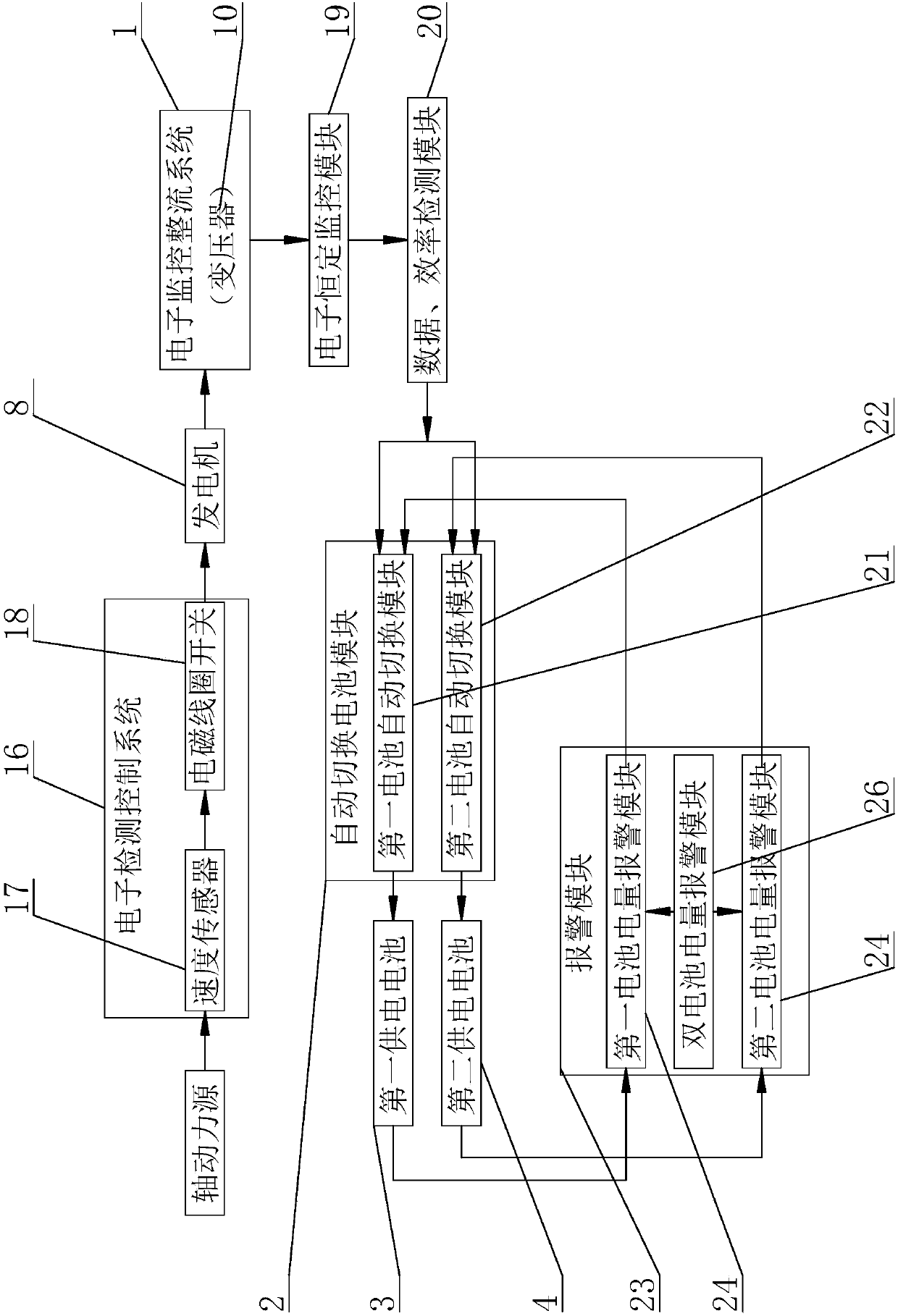
[0045] The present invention is an automatic cycle charging system for an electric vehicle. The main structure includes a shaft power source, a power generation device assembly, an electronic monitoring rectification system 1, an automatic switching battery module 2, a first power supply battery 3 and a second power supply battery 4, Described axle power source comprises the front axle 5 of electric vehicle, rear axle 6, intermediate transmission main shaft 7, and described generating device assembly comprises several generators 8, and the power generation rotating shaft in several described generators 8 can be connected with front axle 5 respectively. , rear wheel shaft 6, intermediate transmission main shaft 7 drive connections, in the prior art, due to the presence and use of bearings on the front wheel shaft 5, rear wheel shaft 6, intermediate transmission main shaft 7, there is a rotating shaft ...

Embodiment 2

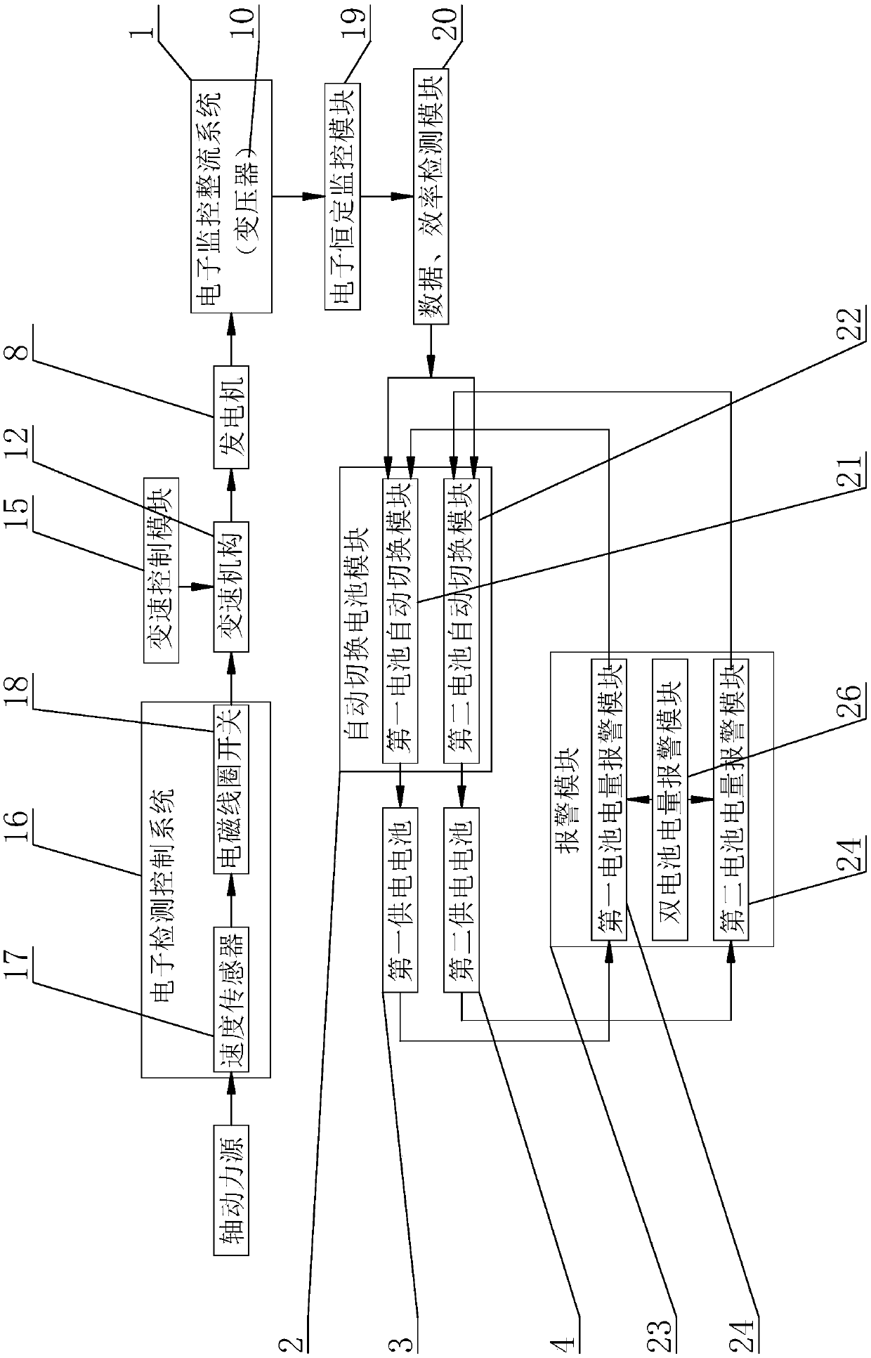
[0050] This embodiment is used for charging electric vehicles powered by AC.

Embodiment 3

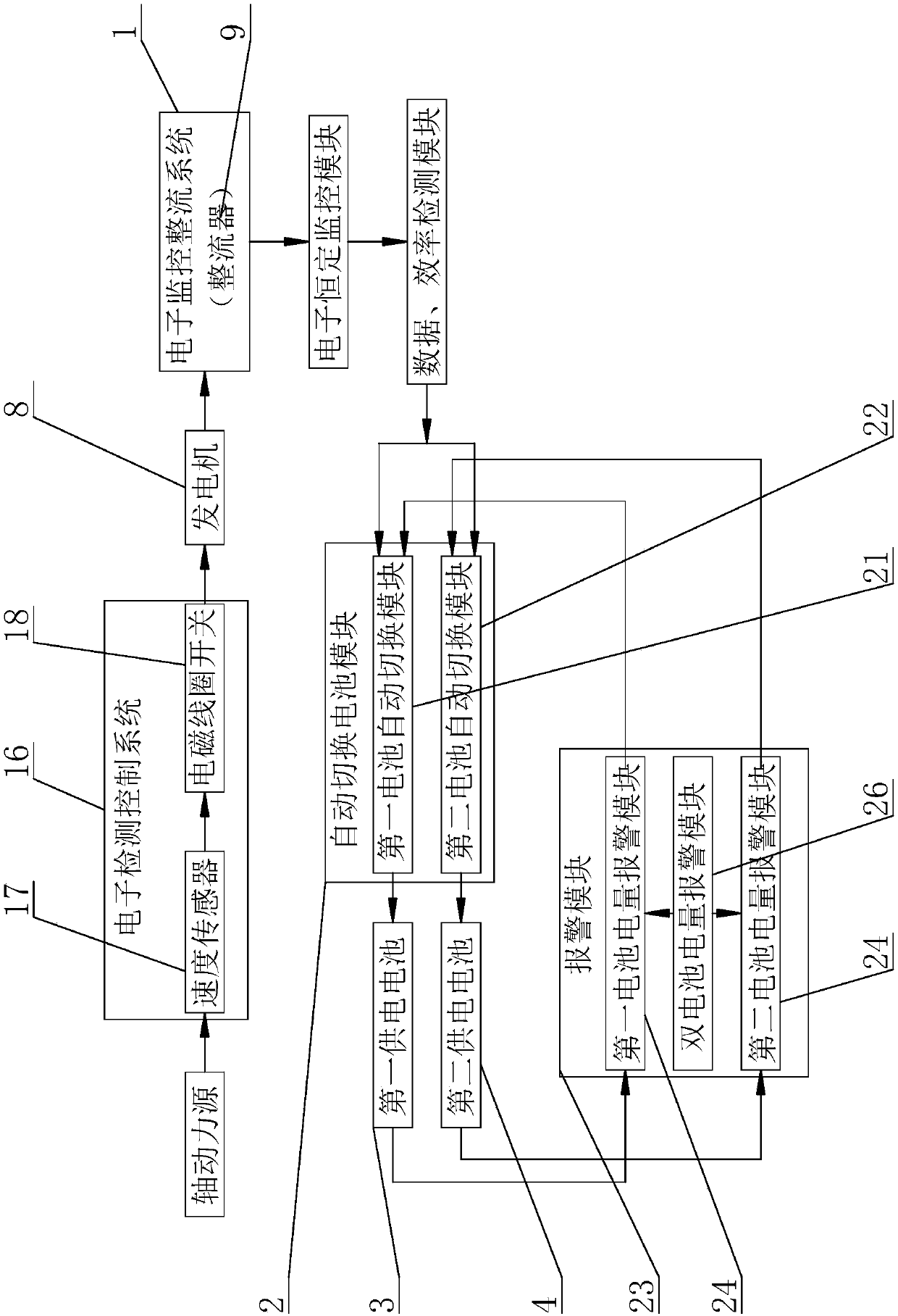
[0053] This embodiment is used for charging electric vehicles powered by direct current.

[0054] Compared with Embodiment 1, the electronic monitoring and rectification system 1 in this embodiment 3 is a rectifier 9, and the rectifier 9 can convert alternating current into direct current, and the electronic monitoring and rectification system 1 processes the current and voltage generated and then supplies power to the first charging device. The battery 3 or the second power supply battery 4 is charged. Other structures, connections and principles of Embodiment 3 are the same as Embodiment 1.


PUM


Abstract

The invention discloses an in-vehicle automatic cycling charging system for an electric vehicle, and mainly relates to the field of charging equipment of the electric vehicle. The in-vehicle automaticcycling charging system comprises a shaft power source, a power generation device assembly, an electronic monitoring rectification system, an automatic switching battery module, a first power supplybattery and a second power supply battery, the power generation device assembly comprises several power generators, power generation rotation shafts in the several power generators can be in drive connection with the shaft power source, the electronic monitoring rectification system is connected with the power generators and is connected with the automatic switching battery module, and the automatic switching battery module is connected with the first power supply battery and the second power supply battery. The in-vehicle automatic cycling charging system for the electric vehicle has the advantages that different degrees of pressure and inconvenience caused by electric power supplement outside electric vehicles all over the world are avoided, and the power supplement is not dependent on external vehicles and communal facilities and equipment anymore. It is achieved that an automatic cycling power supplement system is achieved in traffic tools like a battery electric vehicle, and battery life prolonging can be completed through automatic cycling and automatic charging.

Description

technical field [0001] The invention relates to the field of electric vehicle charging equipment, in particular to an automatic cycle charging system in the electric vehicle. Background technique [0002] Existing vehicles using electricity such as electric vehicles cannot circulate power to themselves as the human heart. Existing vehicles using electricity such as electric vehicles more or less rely on the outside world to complete supplementary electric energy, so as to achieve the purpose of battery life. Under the future development trend, the external charging device will directly affect the development of enterprises and the acceptance of consumers. It will also make users restricted, unable to travel with confidence, and cannot automatically replenish power by itself. It is currently the only one in the world. question. When driving outside, you need to join the public energy replenishment team to recharge and replenish power, which will cause stress and inconvenien...

Claims


Application Information

Patent Timeline
Patent Type & Authority Applications(China)
IPC IPC(8): B60L11/18H02J7/00H02K7/116
CPCB60L58/18B60L58/21H02J7/0068H02K7/116Y02T10/64Y02T10/70Y02T10/72
Inventor 周开全
Owner 周开全
Why Eureka
Try Eureka