
Clutch device

A clutch device, external friction technology, applied in clutches, power devices, friction clutches, etc.

Active Publication Date: 2018-04-17
SCHAEFFLER TECH AG & CO KG
View PDF7 Cites 0 Cited by
  • Summary
  • Abstract
  • Description
  • Claims
  • Application Information

AI Technical Summary

Problems solved by technology

The disadvantage of this type of lubricant accumulation is, on the one hand, that a certain tractive force is generated between the outer and inner friction lining due to a certain backflow of the lubricant and the possibility of a traction (schleppenden) connection between the outer and inner friction linings moment

Method used


Image

  • Clutch device
  • Clutch device
  • Clutch device

Examples


Embodiment Construction

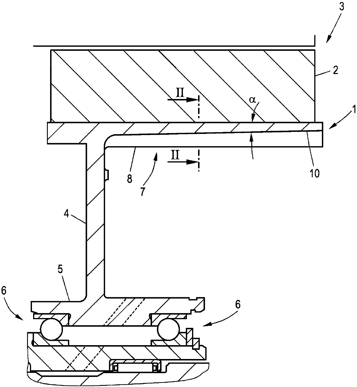
[0023] figure 1 The outer disk carrier 1 according to the invention is shown, in the exemplary embodiment shown, the rotor 2 of the electric machine 3 is connected to the outer disk carrier. As in known solutions, the outer disk carrier 1 is usually part of a known hybrid clutch, which is radially integrated via an annular carrier section 4 and an axially extending bearing section 5 . The position is rotatably supported by the rolling bearing 6.

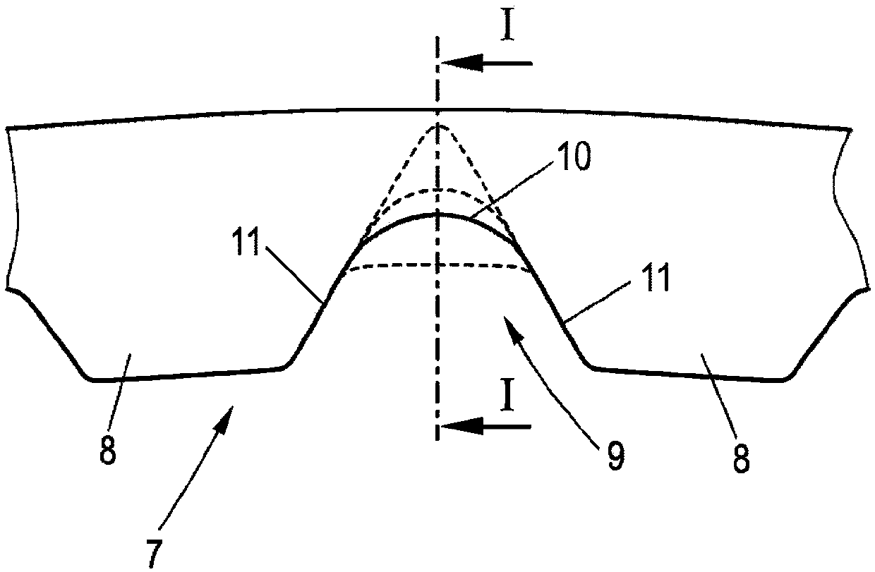
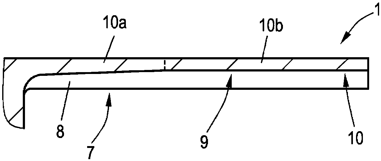
[0024] In known variants, internal toothing 7 is formed on the outer disk carrier 1 , wherein, for the sake of clarity, only the toothing 8 is shown in the sectional view, and not the other toothing rows which are still visible in the sectional view. exist figure 2 The two toothings 8 of the internal toothing 7 are shown in the sectional view along the section line II-II shown in . The teeth 8 are each spaced apart from one another by a groove 9 , wherein the teeth 8 and the grooves 9 extend over the entire length of the outer di...


PUM


Abstract

The invention provides a clutch device. The clutch device includes at least one outer friction sheet support extending axially and a plurality of outer friction sheets, wherein the outer friction sheet support includes inner teeth extending axially and the inner teeth are provided with a plurality of tooth parts spaced from each other by a plurality of grooves extending axially. The outer frictionsheet is provided with outer teeth engaged with the inner teeth. Therefore, with the design of the geometric shape of the groove bottoms, lubricants accumulated in the groove bottoms can be conveyedalong the grooves axially when the outer friction sheet support rotates.

Description

technical field [0001] The invention relates to a clutch device comprising at least one axially extending outer friction plate support and a plurality of outer friction plates, wherein the outer friction plate support comprises axially extending inner teeth, the inner teeth having shafts A plurality of teeth portions spaced apart from each other toward the extending grooves, the outer friction plate has outer teeth meshing with the inner teeth. Background technique [0002] Such clutch devices are used, for example, in clutches of motor vehicles and can be designed in various ways. For example wet single clutches or double clutches are known, in which one clutch device is provided in the single clutch and two clutch devices are provided in the double clutch. Hybrid clutches are also known, which enable the selective connection of an internal combustion engine or an electric machine to a subsequent transmission, wherein, in this case, the rotor of the electric machine is con...

Claims


Application Information

Patent Timeline
IPC IPC(8): F16D25/12
CPCF16D25/123F16D2250/0023B60K6/387F16D13/52F16D13/683F16D13/74F16D2300/0214
Inventor 埃尔马·洛伦兹赖纳·涅库姆
Owner SCHAEFFLER TECH AG & CO KG
Learn More