Impedance testing apparatus

A technology of impedance testing and testing racks, which is applied in measuring devices, measuring resistance/reactance/impedance, measuring electrical variables, etc., can solve problems such as inconvenient use, and achieve simple and convenient operation, good detection accuracy, and stability.

Inactive Publication Date: 2018-04-17
JIANGSU A KERR BIOLOGICAL RECOGNITION TECH CO LTD
View PDF11 Cites 2 Cited by
  • Summary
  • Abstract
  • Description
  • Claims
  • Application Information

AI Technical Summary

Problems solved by technology

[0003] Metal rings are often used in the fingerprint identification modules of electronic products such as mobile phones and tablet computers. Because their function is to ground to prevent the static electricity of the human body from causing damage to the chip when people touch the fingerprint chip, the DC impedance of the metal ring itself is higher. The smaller the better, however, in the current automated testing, a multimeter is used to test its DC impedance, which is very inconvenient to use

Method used


Image

  • Impedance testing apparatus
  • Impedance testing apparatus
  • Impedance testing apparatus

Examples


Embodiment 1

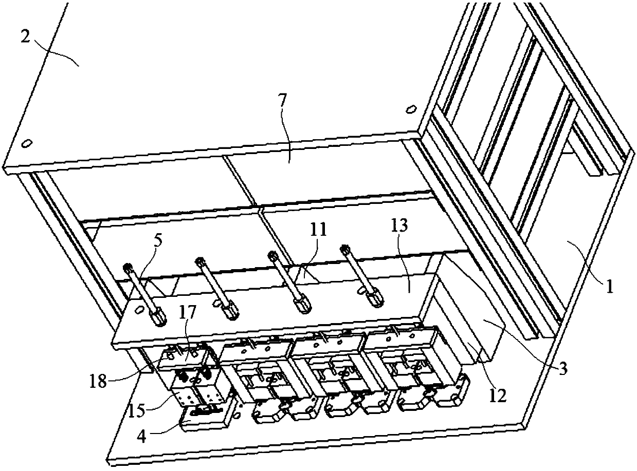
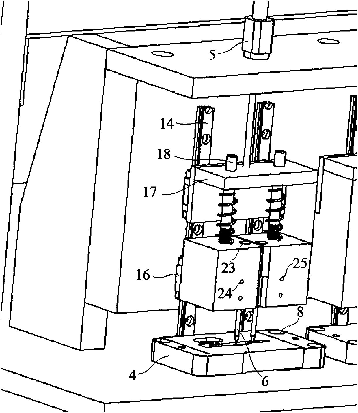
[0025] Embodiment 1: a kind of impedance test device, comprises base 1, support 2, test frame 3, test stage 4, cylinder 5 and probe 6, described support 2 is arranged on the upper surface of base 1 and is provided with several on support 2 Impedance meter 7, the test platform 4 is fixedly installed on the upper surface of the base 1 and below the probe 6 through a number of bolts 8, and the cylinder 5 and the probe 6 are installed on the test frame 3;

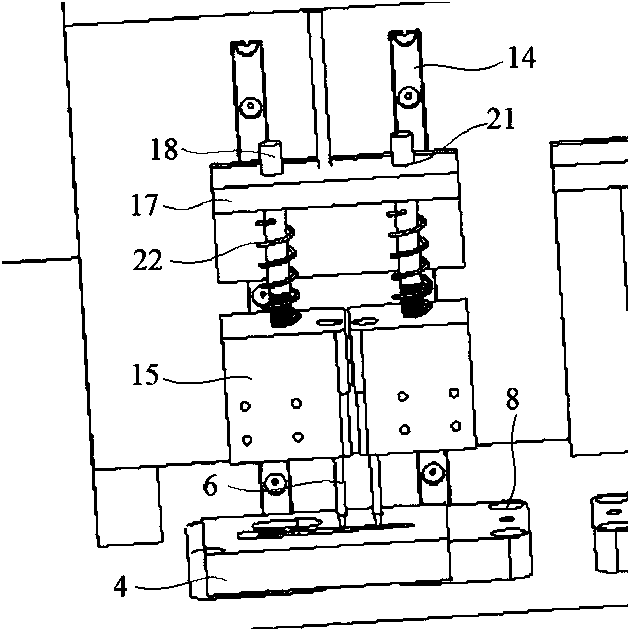
[0026] The test stand 3 further includes a support base 11, a vertical plate 12 and a horizontal plate 13, the vertical plate 12 is fixedly installed on the upper surface of the base 1 through a number of support bases 11, and the horizontal plate 13 is arranged above the vertical plate 12 and horizontally The inner side of the plate 13 is fixedly connected with the upper surface of the vertical plate 12, and the front surface of the vertical plate 12 of the test frame 3 is provided with a plurality of slide rails 14, and a plur...

Embodiment 2

[0030] Embodiment 2: a kind of impedance test device, comprises base 1, support 2, test frame 3, test stage 4, cylinder 5 and probe 6, described support 2 is arranged on the upper surface of base 1 and is provided with several Impedance meter 7, the test carrier 4 is fixedly installed on the upper surface of the base 1 by several bolts 8 and is located below the probe 6, and the cylinder 5 and the probe 6 are installed on the test frame 3;

[0031]The test stand 3 further includes a support base 11, a vertical plate 12 and a horizontal plate 13, the vertical plate 12 is fixedly installed on the upper surface of the base 1 through a number of support bases 11, and the horizontal plate 13 is arranged above the vertical plate 12 and horizontally The inner side of the plate 13 is fixedly connected with the upper surface of the vertical plate 12, and the front surface of the vertical plate 12 of the test frame 3 is provided with a plurality of slide rails 14, and a plurality of prob...


PUM


Abstract

The invention discloses an impedance testing apparatus comprising a base, a bracket, a test rack, a test carrier bench, an air cylinder and probes. The bracket is arranged on the upper surface of thebase and a plurality of impedance meters are arranged on the bracket. The test carrier bench is fixedly installed on the upper surface of the base by a plurality of bolts and is arranged below the probes. The probes are arranged in a plurality of probe bases. A spring sleeves the outer side of a connecting post; double-screw bolt hole and mounting holes are communicated. The probes are embedded into the mounting holes formed in the low surface of the probe bases from bottom to top and are fixedly connected with the probe bases by double-screw bolts embedded in the double-screw bolt holes. Thebolts are formed by bolt caps and bolt rods; and threads are formed at the outer surfaces of the bolt rods. A T-shaped hole is formed by a second through hole and a first through hole that are communicated left and right. The diameter of the double-screw bolt is smaller than that of the second through hole; and the threads of the bolts match threaded holes of the test carrier bench. With a supportbase, stability of the test rack is ensured and thus the stability of the test accuracy is guaranteed.

Description

technical field [0001] The invention relates to a device testing device, in particular to an impedance testing device. Background technique [0002] With the development of science and technology, electronic sensing technology is being applied more and more. Fingerprint identification technology is currently the most mature and cheap biometric identification technology. At present, the fingerprint recognition technology is the most widely used. We can not only see the fingerprint recognition technology in the access control and attendance system, but also have more fingerprint recognition applications in the market: such as laptops, mobile phones, cars, bank payments, etc. Fingerprint recognition technology can be applied. [0003] Metal rings are often used in the fingerprint identification modules of electronic products such as mobile phones and tablet computers. Because they are used as grounding to prevent the static electricity of the human body from causing damage to...

Claims


Application Information

Patent Timeline
Patent Type & Authority Applications(China)
IPC IPC(8): G01R27/02
CPCG01R27/02
Inventor 陈东王凯姜海光王海昌位贤龙袁涛
Owner JIANGSU A KERR BIOLOGICAL RECOGNITION TECH CO LTD
Why Eureka
Try Eureka