
Composite net-shaped grid manufacturing equipment for storage battery

A technology for manufacturing equipment and batteries, applied in battery electrodes, circuits, electrical components, etc., can solve the problems of short battery life, poor corrosion resistance of sulfuric acid, damage to ecology, etc., and achieve the effect of improving production efficiency

Active Publication Date: 2018-04-17
肇庆中特能科技投资有限公司
View PDF4 Cites 6 Cited by
  • Summary
  • Abstract
  • Description
  • Claims
  • Application Information

AI Technical Summary

Problems solved by technology

[0003] The grid is heavy, has poor corrosion resistance to sulfuric acid, and has a short battery life. Moreover, lead pollution seriously damages the ecology, and the country will phase it out. In order to reduce weight and avoid lead pollution, a composite mesh battery has been developed. It uses carbon fiber coaxial composite zinc wire (that is, a composite material formed by uniformly covering the surface of carbon fiber core wire with zinc alloy) or carbon fiber coaxial composite graphene to make the grid, which is not only light in weight, but also meets environmental protection requirements. , and prolong battery life
[0004] At present, there is no special equipment for making composite wires such as carbon fiber coaxial composite zinc wire or carbon fiber coaxial composite graphene into grids

Method used


Image

  • Composite net-shaped grid manufacturing equipment for storage battery
  • Composite net-shaped grid manufacturing equipment for storage battery
  • Composite net-shaped grid manufacturing equipment for storage battery

Examples


Embodiment Construction

[0025] Embodiments of the technical solutions of the present invention will be described in detail below in conjunction with the accompanying drawings. The following examples are only used to illustrate the technical solution of the present invention more clearly, and therefore are only examples, and should not be used to limit the scope of protection of this patent.

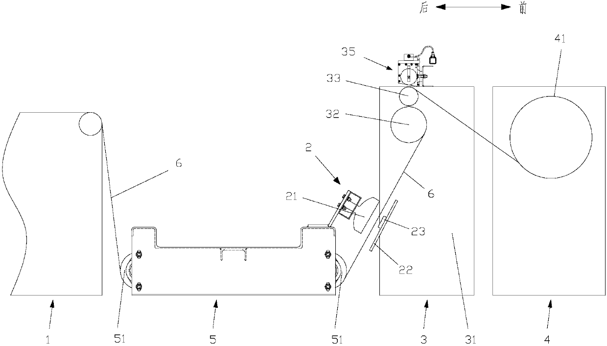
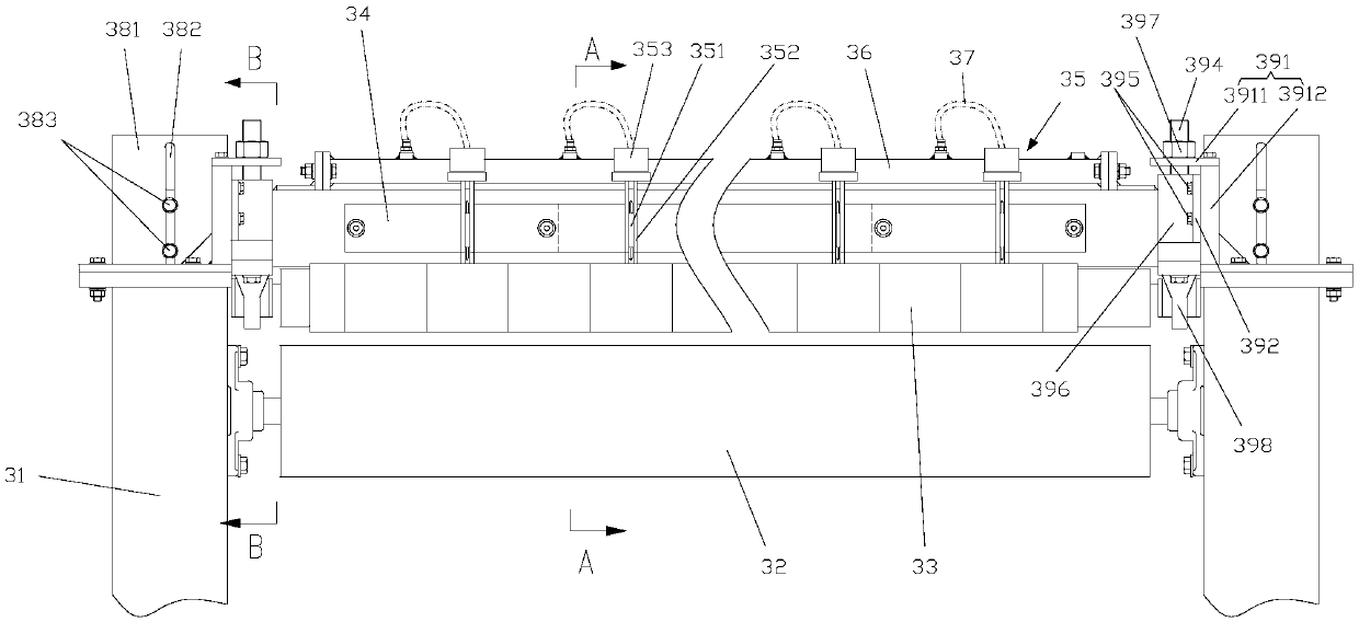
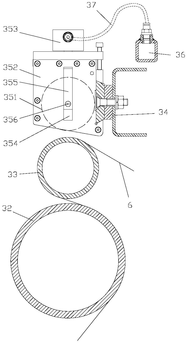
[0026] like Figure 1-Figure 5 As shown, the embodiment of the present invention provides a composite mesh grid manufacturing equipment for batteries, including: a braiding machine 1, used to weave the grid composite wire 61 and the hot-melt wire 62 into a composite grid 6, the The composite grid 6 is divided into several grid strips along the warp line according to the set width, and the edges of each grid strip both sides are woven with hot-melt lines 62 (such as Figure 5 shown in the thick solid line), in the present embodiment, the grid composite wire 61 can be a carbon fiber coaxial composite zinc wire or...


PUM

PropertyMeasurementUnit
diameteraaaaaaaaaa
diameteraaaaaaaaaa
diameteraaaaaaaaaa

Abstract

The invention discloses composite net-shaped grid manufacturing equipment for a storage battery. The composite net-shaped grid manufacturing equipment comprises a weaving machine, a heating mechanism,a cutting mechanism and a take-up mechanism, wherein the weaving machine is used for weaving grid composite lines and hot-melting lines to form a composite grid net, the composite grid net is dividedinto a plurality of grid strips along meridians according to a set width, the hot-melting lines are woven at edges of two sides of each grid plate, the heating mechanism is used for heating the hot-melting lines woven in the composite grid net so that the hot-melting lines are molten and are pasted with wefts of the composite grid net, the cutting mechanism is used for cutting the meridian between two adjacent grid strips so that the composite grid net is cut to form the plurality of independent grid strips and is simultaneously used for cutting redundant parts of edges of the grid strips ata left end and a right end, the take-up mechanism comprises a plurality of take-up units, and each take-up unit is used for correspondingly winding each grid strip. By the composite net-shaped grid manufacturing equipment, weaving, edge locking, cutting and take-up of the composite grid net can be achieved, each process is continuously operated, and the production efficiency is improved.

Description

technical field [0001] The invention relates to the technical field of accumulators, in particular to a composite mesh grid manufacturing equipment for accumulators. Background technique [0002] The grid is the main component of the battery, and its functions in the battery are: 1. Support the active material; 2. Make the current evenly distributed on the active material to improve the utilization rate of the active material. There are two traditional manufacturing methods of grids: stretching and casting. Among them, casting is to pour heated and melted lead alloy into the grid mold under the action of gravity, then cool and form, and then process; stretching is to pour a certain width of lead alloy The lead strip is made into a prescribed rectangular hole on a punching machine, stretched and formed. [0003] The grid is heavy, has poor corrosion resistance to sulfuric acid, and has a short battery life. Moreover, lead pollution seriously damages the ecology, and the coun...

Claims


Application Information

Patent Timeline
Patent Type & Authority Applications(China)
IPC IPC(8): H01M4/73H01M4/74H01M4/82D04H5/06D06H7/00
CPCD04H5/06D06H7/00H01M4/73H01M4/747H01M4/82Y02E60/10
Inventor 何可立何幸华李政文高明
Owner 肇庆中特能科技投资有限公司
Learn More