Method for manufacturing graphite shaft

A graphite shaft and shaft technology, which is applied in the field of manufacturing graphite shafts reinforced at least in part by fillers, can solve the problems of increasing the weight of golf clubs, reducing the weight of golf club heads, destroying balance and the like, and achieving torque reduction, The effect of improved flight distance and directivity

Active Publication Date: 2018-04-17
林正洙
View PDF7 Cites 0 Cited by
  • Summary
  • Abstract
  • Description
  • Claims
  • Application Information

AI Technical Summary

Problems solved by technology

However, the weight of the entire golf club has to be increased due to the weight of the filler, which leads to a breakdown in the balance of the shaft
As a solution to this imbalance, there is a need to reduce the weight of the golf club head, but this creates another unfavorable problem

Method used


Image

  • Method for manufacturing graphite shaft
  • Method for manufacturing graphite shaft
  • Method for manufacturing graphite shaft

Examples


Embodiment Construction

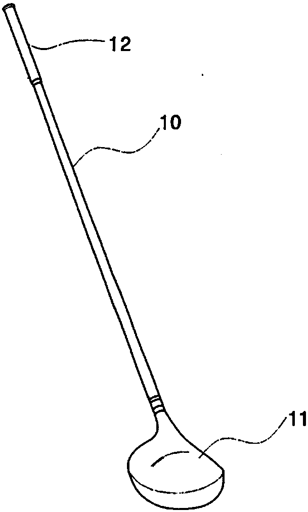
[0035] A method for manufacturing a graphite shaft according to the present invention will be described in detail with reference to the accompanying drawings.

[0036] In the following description, for the sake of simplicity, a method for manufacturing a graphite shaft for golf clubs is described, but it will be apparent to those of ordinary skill in the art that the principles of the present invention should not be limited to golf used with clubs.

[0037] Accordingly, it should be understood that the methods according to the present invention are equally applicable to graphite shafts that may be used with other sporting equipment and everyday items.

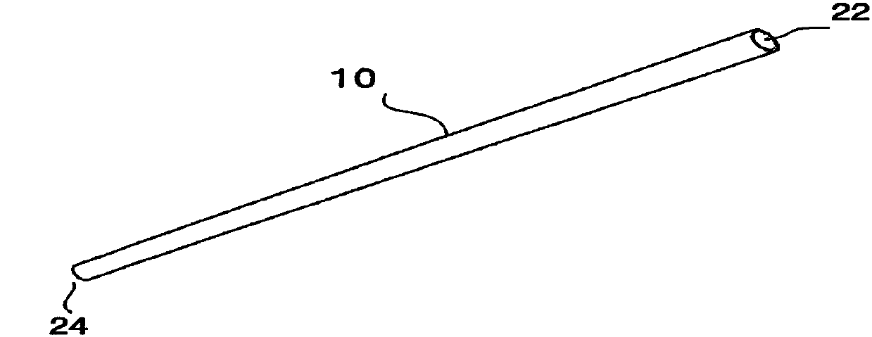
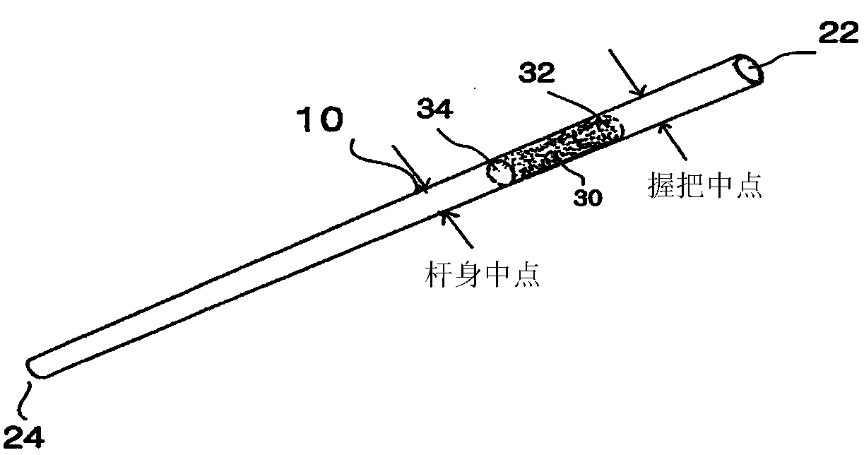
[0038] In the following description, the "proximal portion" of the shaft refers to the end portion of the shaft of the golf club or fishing rod where the grip is mounted, ie, the end portion close to the user. Furthermore, the "distal portion" of the shaft is the end portion on the opposite side of the proximal portion, ie the...


PUM


Abstract

A method for producing a graphite shaft comprises the steps of: preparing a tube made of a synthetic resin into which a thermosetting resin powder is put; inserting the synthetic resin tube into the finished product graphite shaft; closing an upper end of the graphite shaft; and placing the graphite shaft in a high-temperature pressurizing apparatus and then heating the same so that the thermosetting resin powder is foamed and filled in a part of the interior of the shaft.

Description

technical field [0001] The present application relates to methods for manufacturing graphite shafts, and more particularly, to methods of manufacturing graphite shafts at least partially reinforced with a filler. The graphite shaft manufactured according to the method of the present invention can be used for golf clubs, fishing rods and the like. Background technique [0002] A golf club generally consists of a club head to hit the golf ball, a grip, and a shaft attached to the club head. Golfers typically choose steel or graphite shafts based on their size and swing speed. [0003] Golf clubs with steel shafts have a higher rate of meeting the sweet spot due to their lower torque in the swing, and therefore, the golf ball is highly directional. However, since the steel shaft is heavy and has low elasticity, it is not easy to increase the flight distance of the golf ball without the support of the golfer's physical strength and high swing speed. [0004] On the other hand...

Claims


Application Information

Patent Timeline
Patent Type & Authority Applications(China)
IPC IPC(8): B29C70/44A01K85/00A01K87/00A63B53/10B29C35/02B29C44/00
CPCA63B53/10B29C35/02B29K2105/251B29K2101/10B29C70/446A01K87/00B29C44/18B29K2105/04B29K2707/04B29L2031/5227B29L2031/7002A63B2209/00A63B2102/32B29C70/44
Inventor 林正洙
Owner 林正洙
Why Eureka
Try Eureka