
Pneumatic valve drive

A valve-driven, pneumatic cylinder technology, applied in the direction of fluid pressure actuation device, servo motor, servo meter circuit, etc., can solve the problem of cumbersome adjustment technology and so on

Active Publication Date: 2018-04-17
VAT HLDG AG
View PDF10 Cites 0 Cited by
  • Summary
  • Abstract
  • Description
  • Claims
  • Application Information

AI Technical Summary

Problems solved by technology

This is rather cumbersome technically to regulate

Method used


Image

  • Pneumatic valve drive
  • Pneumatic valve drive
  • Pneumatic valve drive

Examples


Embodiment Construction

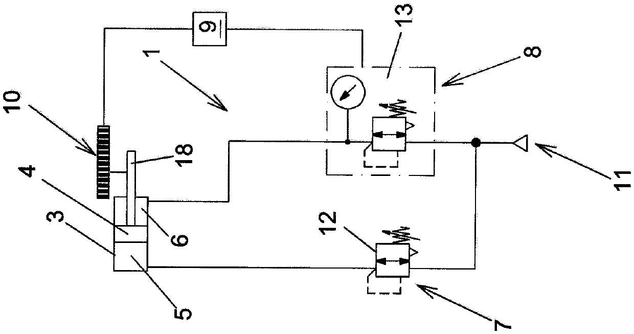
[0025] Figures 1 to 3 Various exemplary embodiments are shown in which the pneumatic valve drive 1 according to the invention has only a single piston-cylinder unit in the form of a pneumatic cylinder 3 with a piston 4 movably arranged therein. Such a pneumatic valve drive can be used, for example, when the closing member 15 has only to be moved back and forth along a straight line or parallel thereto in order to close and release the valve opening 16, such as in the very schematically shown according to Image 6 with 7 This is the case in the valve.

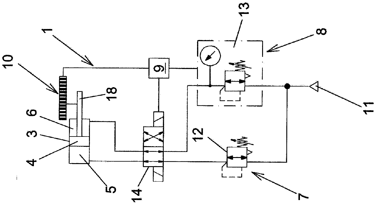
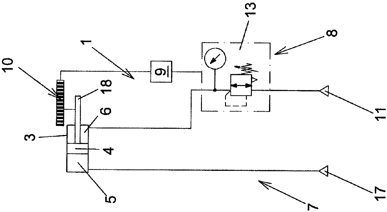
[0026] Now first introduce the basis of figure 1 the embodiment. Then explain the basis figure 2 with 3 The embodiment and basis figure 1 difference between the examples. Leaving aside the distinction to be expounded later, according to figure 1 The description of the example can also be applied according to figure 2 with 3 variant design.

[0027] exist figure 1 It can be clearly seen in the figure that the p...


PUM


Abstract

The invention relates to a pneumatic valve drive (1) for a valve (2), in particular for a vacuum valve, which has at least one pneumatic cylinder (3) with at least one piston (4) that is movably mounted in the pneumatic cylinder (3) and at least two cylinder cavities (5, 6) arranged on opposite sides of the piston (4). Each cylinder cavity (5, 6) is connected to at least one pressure source for applying pressure to each cylinder cavity (5, 6). One of the pressure sources is a constant pressure source (7) for applying a constant pressure to the cylinder cavity (5) arranged on one of the sides of the piston, and one of the other pressure sources is a regulated pressure source (8) for applying a variably regulatable pressure to the cylinder cavity (6) arranged on the opposite side of the piston (4).

Description

technical field [0001] The invention relates to a pneumatic valve drive for a valve, in particular a vacuum valve, having at least one pneumatic cylinder with at least one piston movably arranged in the pneumatic cylinder and with At least two cylinder cavities arranged on opposite sides of the piston, wherein each cylinder cavity is connected to at least one pressure source in order to pressurize the respective cylinder cavity. [0002] Furthermore, the invention relates to a method for operating such a pneumatic valve drive, and also to a valve, in particular a vacuum valve, having at least one such pneumatic valve drive. Background technique [0003] In the case of valves, in particular vacuum valves, a pneumatic valve drive is usually used in order to drive a closing mechanism, for example, in order to close and / or release the valve opening of the valve. Compared with the hydraulic valve driving device, the pneumatic valve driving device has the following advantages: wh...

Claims


Application Information

Patent Timeline
Patent Type & Authority Applications(China)
IPC IPC(8): F15B11/046F15B15/20F15B15/28
CPCF15B11/046F15B15/202F15B2211/27F15B15/2815F15B11/10F15B15/04F15B2211/329F15B2211/7053
Inventor 克里斯托夫·伯姆艾德里安·埃申莫瑟
Owner VAT HLDG AG
Features
  • Generate Ideas
  • Intellectual Property
  • Life Sciences
  • Materials
  • Tech Scout
  • Unparalleled Data Quality
  • Higher Quality Content
  • 60% Fewer Hallucinations
Learn More