Temperature sensor

A temperature sensor and sensor technology, applied in thermometers, thermometer parts, instruments, etc., can solve the problems of decreased responsiveness, increased heat capacity and contact area, and achieve improved responsiveness, small heat capacity, and high responsiveness Effect

Inactive Publication Date: 2018-04-17
MITSUBISHI MATERIALS CORP
View PDF7 Cites 0 Cited by
  • Summary
  • Abstract
  • Description
  • Claims
  • Application Information

AI Technical Summary

Problems solved by technology

[0010] In addition, in the technology described in Patent Document 2, as in the technology described in Patent Document 1, if the protective tape is also attached to the contact surface side of the insulating film and used, the lead frame and the protective tape will be separated. An insulating film is inserted between the tapes so that the measurement object is less likely to be damaged, but the heat capacity and contact area increase due to further overlapping and bonding of a wider protective tape on a wider insulating film, resulting in a decrease in responsiveness. concern

Method used


Image

  • Temperature sensor
  • Temperature sensor
  • Temperature sensor

Examples


Embodiment Construction

[0027] Below, refer to Figure 1 to Figure 4 One embodiment of the temperature sensor of the present invention will be described. In addition, in a part of the drawings used in the following description, the scale is appropriately changed as necessary in order to make each part recognizable or easily recognizable.

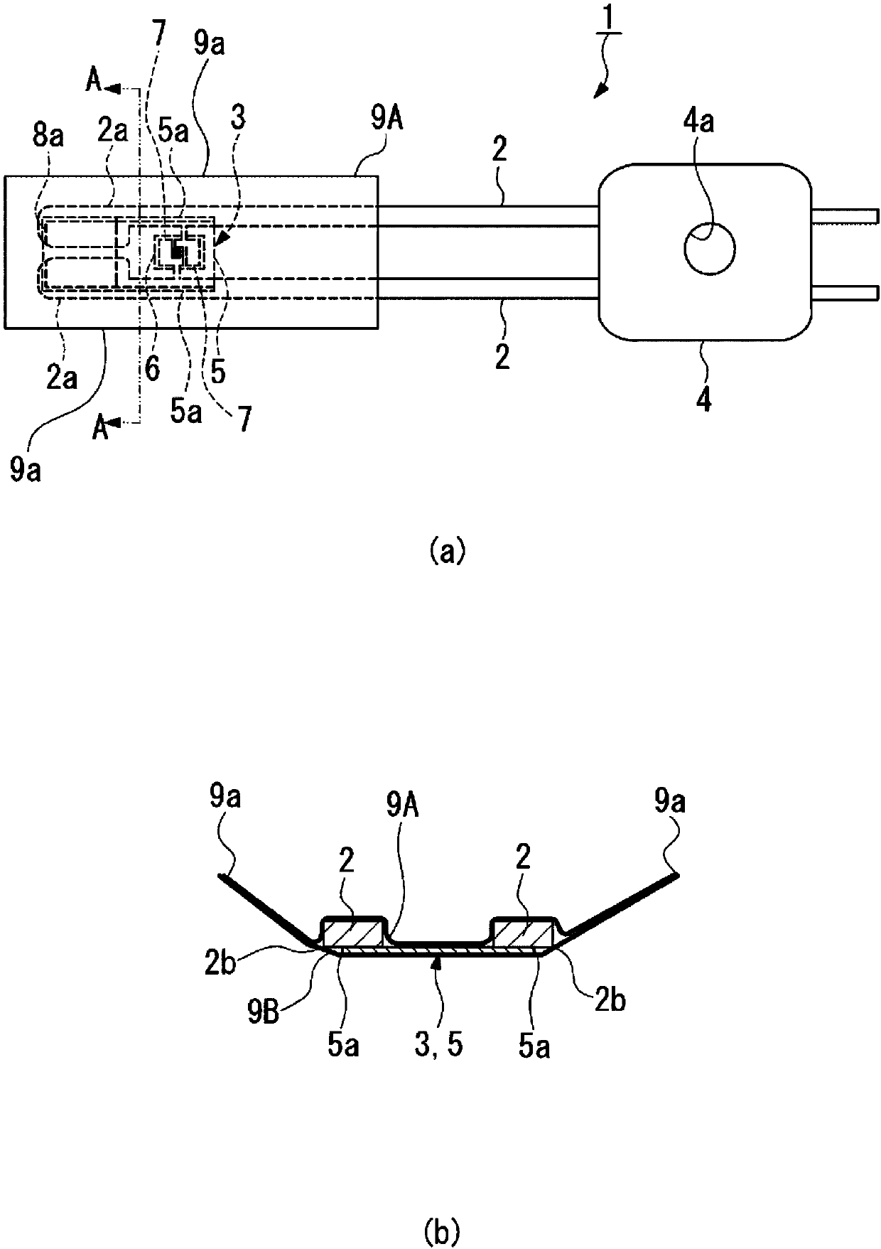
[0028] like figure 1 As shown, the temperature sensor 1 of this embodiment includes a pair of lead frames 2, a sensor part 3 connected to the pair of lead frames 2, and a holding part 4 fixed to the pair of lead frames 2 to hold the pair of lead frames 2 insulated. .

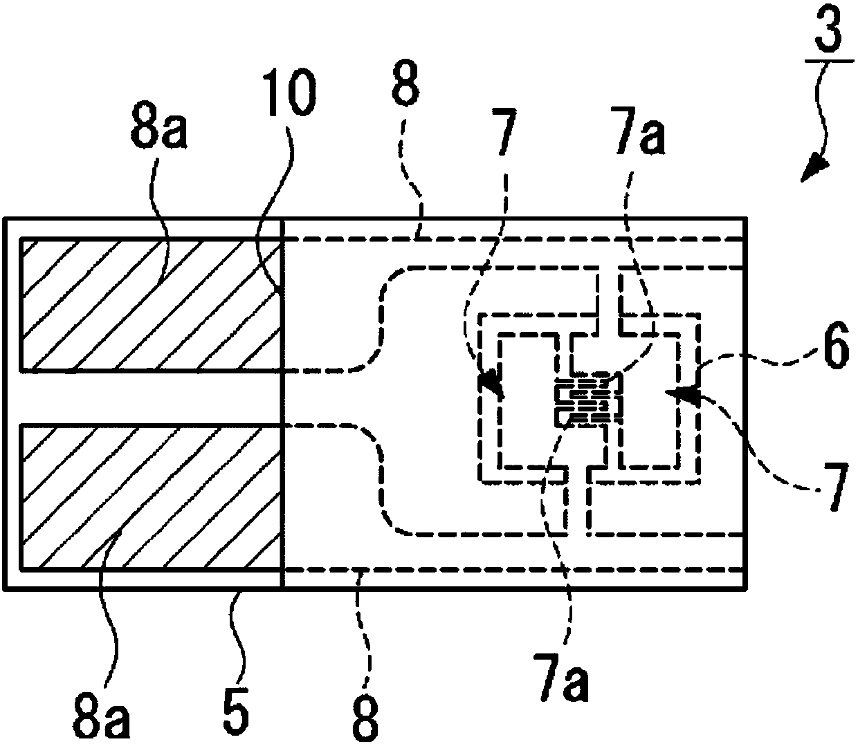
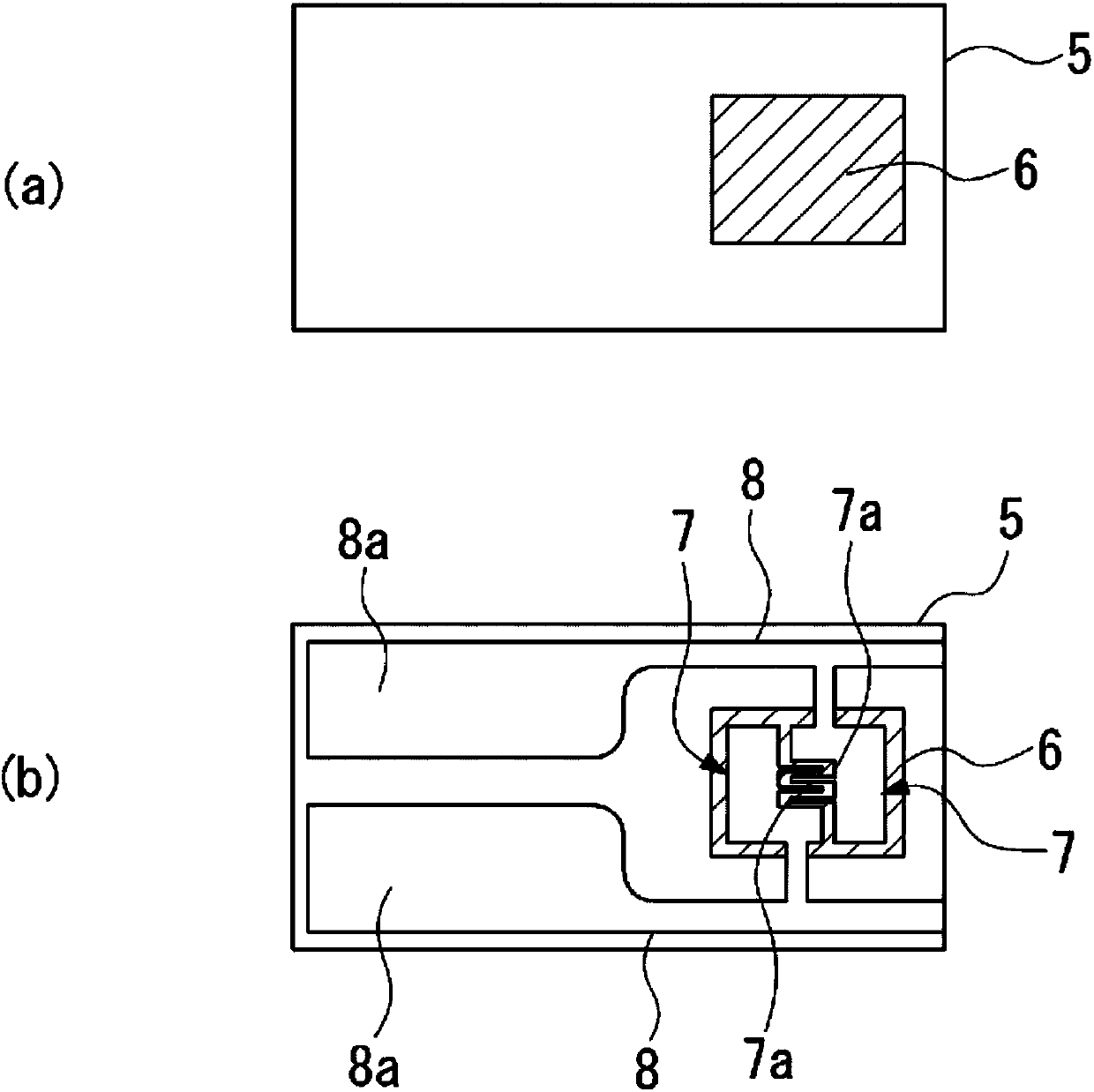
[0029] The sensor unit 3 includes an insulating film 5 on which a pair of lead frames 2 are adhered on the upper surface, a thin film thermistor unit 6 pattern-formed on the upper surface of the insulating film 5 from a thermistor material, A pair of comb electrodes 7 having a plurality of comb portions 7a and patterned to face each other on the resistance portion 6 is connected to the pair of co...


PUM

PropertyMeasurementUnit
thicknessaaaaaaaaaa
thicknessaaaaaaaaaa
thicknessaaaaaaaaaa

Abstract

A temperature sensor of the present invention is provided with a pair of lead frames 2, a sensor section 3 connected to the lead frames, and an insulating holding section 4 that holds the lead frames.The sensor section is provided with: an insulating film 5 having the lead frames bonded on the upper surface; a thin film thermistor section 6 formed on the insulating film; a pair of interdigital electrodes 7 formed on the thin film thermistor section; a pair of pattern electrodes formed on the upper surface of the insulating film; and a pair of protection tapes 9A, 9B, which are bonded to eachother by vertically sandwiching therebetween the pair of lead frames and the sensor section. Both side sections 5a of the insulating film are disposed close to and on the inner sides of outer corner sections 2b that are disposed on the bonding surface sides of the pair of lead frames, and both side sections 9a of the protection tapes are bent on the outer side of both the side sections of the insulating film, said side sections 9a being bent toward the upper surface side.

Description

technical field [0001] The present invention relates to a temperature sensor suitable for measuring the temperature of heating rollers of copiers, printers, etc., and having excellent responsiveness. Background technique [0002] Generally, in order to measure the temperature of the heating roller used in copiers and printers, a temperature sensor is provided in a contact state. As such a temperature sensor, for example, Patent Document 1 proposes a temperature sensor including a pair of lead frames, a thermosensitive element arranged and connected between these lead frames, and a temperature sensor formed at the ends of the pair of lead frames. The holding part and the protective tape (film sheet) provided on one side of the lead frame and the thermal element and in contact with the heating roller. [0003] In the aforementioned Patent Document 1, in addition to spherical thermistors and chip thermistors, thin film thermistors in which a thermal film is formed on one side ...

Claims


Application Information

Patent Timeline
Patent Type & Authority Applications(China)
IPC IPC(8): G01K7/22
CPCG03G15/2039G01K1/12G01K7/223
Inventor 长友宪昭松本文夫稻叶均竹岛一太山口邦生田中宽
Owner MITSUBISHI MATERIALS CORP
Why Eureka
Try Eureka