Process for non-destructive testing using direct strain imaging

A non-destructive testing and process technology, applied in elastic testing, using stable tension/pressure testing for material strength, fuel testing, etc., can solve problems such as destroying test pieces

Inactive Publication Date: 2018-04-17
AEROJET ROCKETDYNE INC
View PDF9 Cites 1 Cited by
  • Summary
  • Abstract
  • Description
  • Claims
  • Application Information

AI Technical Summary

Problems solved by technology

Of course, this measurement...

Method used


Image

  • Process for non-destructive testing using direct strain imaging
  • Process for non-destructive testing using direct strain imaging
  • Process for non-destructive testing using direct strain imaging

Examples


Embodiment Construction

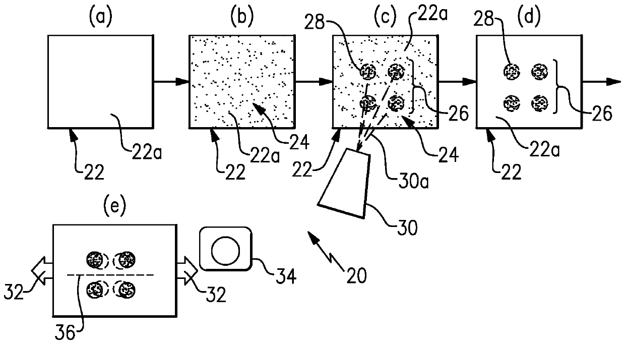
[0026] figure 1 A process 20 for non-destructive testing using direct strain imaging is schematically shown. While basic strain imaging is known, it is currently not suitable for high-volume testing, fabrication or complex geometries. As will be described, process 20 provides the ability to quickly prepare articles for direct strain imaging that are suitable for use with manufactured articles and can be used with articles having complex shapes.

[0027] Process 20 is described with respect to stages (a), (b), (c), (d) and (e), but it is understood that stages may represent combined method operations or may be combined or further subdivided. Phase (a) begins with the item 22 (item body) to be subjected to non-destructive testing. Such non-destructive testing may be performed for a variety of reasons including, but not limited to, quality assurance of manufactured articles, article design evaluation, finite element analysis verification, and article aging effects. Article 22 ...


PUM


Abstract

A process for non-destructive testing includes applying a photo-curable dye to a surface of an article, selectively curing an array of dots of the photo-curable dye on the surface, removing the photo-curable dye that has not been selectively cured, mechanically testing the article, and direct strain imaging the article during the mechanical testing based on the array of dots.

Description

technical field [0001] This application claims priority to US Provisional Application No. 62 / 209,148, filed August 24, 2015. Background technique [0002] For example, mechanical strain measurements are often performed for materials testing. At the most basic level, mechanical strain measurement involves permanently deforming a test piece and then measuring how much the test piece is deformed in order to determine strain. Of course, this measurement technique destroys the test piece. [0003] Strain can also be measured via imaging. For example, placing markers on flat material test specimens. Acquire an initial image of the marker with the test specimen at rest. The test coupon is then subjected to mechanical force and a second image of the mark is acquired. Strain was determined by the difference in the position of the markers between the initial image and the second image. Contents of the invention [0004] A process for non-destructive testing according to an exa...

Claims


Application Information

Patent Timeline
IPC IPC(8): G01N3/00G01M5/00G01N33/22G01N3/08G01B11/16G01N33/00
CPCG01M5/00G01N3/00G01N33/222G01N2203/0003G01N2203/0647G01N2203/0652G01N2203/0682G01B11/165G01B11/16G01N2033/0078G01L1/241G01N3/02
Inventor A.H.克鲁埃西
Owner AEROJET ROCKETDYNE INC
Why Eureka
Try Eureka