Mold frame provided with displaceable beating device

A mold base and displacement technology, applied in metal processing equipment, forming tools, manufacturing tools, etc., can solve problems that cannot be adapted to the processing of fine and diversified metal sheet metal parts, the production cost of turret CNC punching machines is high, and there is no maintenance. Qualification and other issues, to achieve the effect of simple structure, precise movement control, and high degree of automation

Pending Publication Date: 2018-04-20
吕子元
View PDF0 Cites 1 Cited by
  • Summary
  • Abstract
  • Description
  • Claims
  • Application Information

AI Technical Summary

Problems solved by technology

Due to the single mold of ordinary forging equipment, generally only one pair of molds or continuous molds are installed, which can only process the blanking or forming of one product, and the guide pillars are installed on the mold, which has limitations on the shape and size of the product, so it can only be processed according to the forging equipment. It is no longer suitable for the processing of fine and diversified hardware sheet metal parts.
The turret type CNC punching machine includes an upper die and a lower die. The upper die is equipped with a number of punches through a rotatable shaft, and the lower die is provided with a die corresponding to each punch of the upper die through a turntable. When working Rotate the shafts of the upper and lower dies through the control device, rotate the required punches and dies to the worktable, and then guide the guide pins to make the punches and dies precisely aligned. Because the processing of the upper and lower turntables is very difficult, it is very difficult to control the rotation of the upper and lower dies. The positioning accuracy of the turntable is also high, so the production cost of the turret CNC punching machine is very high. In addition, when the turret CNC punching machine breaks down, ordinary technicians do not have the qualifications for maintenance, and professional technicians are required to repair it.
For this reason, many manufacturers and people of insight have carried out development and research, but so far no satisfactory products have come out.

Method used


Image

  • Mold frame provided with displaceable beating device
  • Mold frame provided with displaceable beating device
  • Mold frame provided with displaceable beating device

Examples


Embodiment Construction

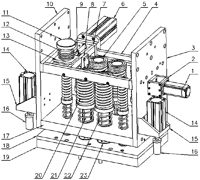
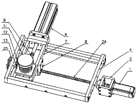
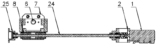
[0020] Figure 1 to Figure 5 As shown, a mold base equipped with a displaceable hitting device is created for the present invention, which includes left and right connecting plates 10, 3, an upper mold fixing plate 17, a lower mold fixing plate 18, a beating mechanism, and an upper mold fixing plate 17. There are punching units with several stations on it, and the lower die fixing plate 18 is provided with a lower die core 23 corresponding to the punching unit. The striking moving frame 7, the striking seat cylinder 6, the striking head 11, the striking return spring 12, the striking seat 13, the left and right connecting plates 10 and 3, the striking fixing frame 4 and the upper die fixing plate 17 are mutually formed and fixed on the punch press. The upper die frame on the frame 32; the striking moving frame 7 is set on the striking fixed frame 4 so as to be movable left and right; the striking seat 13 is set on the striking moving frame 7 so as to be movable back and forth;...


PUM


Abstract

The invention discloses a mold frame equipped with a displaceable striking device, comprising left and right connecting plates (10, 3), upper and lower die fixing plates (17, 18), and a striking mechanism, the striking mechanism includes a motor (1), transmission rod (24), hit fixed frame (4), hit moving frame (7), hit seat cylinder (6), hit head (11), hit seat (13), hit and move The frame (7) is arranged on the hitting fixed frame (4), the hitting seat (13) is arranged on the hitting mobile frame (7), and the hitting head (11) is arranged on the hitting seat (13); The cylinder (6) is connected with the hitting seat (13) and can drive the hitting seat (13) to slide forward and backward; the driving rod connecting seat (8) is fixed on the hitting mobile frame (7), and the motor (1) passes through the driving rod ( 24) Cooperate with the transmission rod connecting seat (8) to drive the hitting mobile frame (7) to move left and right. After adopting the above structure, it has the advantages of reasonable structural design, simple operation, fast moving response speed, high degree of automation, stable and reliable operation, convenient maintenance and high work efficiency.

Description

technical field [0001] The invention relates to a die set of a numerically controlled punching machine, in particular to a die set equipped with a displaceable striking device suitable for the stamping processing of large metal sheet metal parts. Background technique [0002] At present, there are two main types of stamping processing of metal sheet metal parts, one is stamping with ordinary forging equipment, and the other is stamping with a very expensive turret-type CNC punch with a multi-station punch. Ordinary forging equipment, due to the single mold, generally only installs one pair of molds or continuous molds, and can only process the blanking or forming of one product, and there are guide posts installed on the mold, which limits the size of the product, only according to the forging equipment. It is not suitable for the processing of fine and diversified metal sheet metal parts. The turret type CNC punching machine includes an upper die and a lower die. The upper...

Claims


Application Information

Patent Timeline
Patent Type & Authority Applications(China)
IPC IPC(8): B21D37/10B21D37/12B21D37/04
CPCB21D37/10B21D37/04B21D37/12
Inventor 吕子元
Owner 吕子元
Why Eureka
Try Eureka