
Device capable of clearing away drilling winding scraps

A technology for installing grooves and fixing brackets, which is used in drilling/drilling equipment, components of boring machines/drilling machines, metal processing equipment, etc., which can solve the problem of high labor intensity, low processing efficiency of drilling process, and no effective avoidance of iron filings. It can reduce the cost of cutting tools, improve the efficiency of drilling processing, and simplify the manual operation process.

Inactive Publication Date: 2018-04-20
SHENYANG LIMING AERO-ENGINE GROUP CORPORATION
View PDF6 Cites 4 Cited by
  • Summary
  • Abstract
  • Description
  • Claims
  • Application Information

AI Technical Summary

Problems solved by technology

However, since most CNC equipment does not have the function of high-pressure chip breaking, and there is no method to effectively avoid the winding of iron filings and the automatic cleaning of iron filings in the process, the operator still needs to pay attention to the winding of iron filings at any time during the CNC drilling process, and timely increase Worker intervention can ensure timely cleaning of iron filings on the tool and ensure that the tool does not break due to entanglement of chips
The downtime for cleaning iron filings is more than pure cutting time, and with the increase in the number of drilling holes and the increase in drilling depth, the downtime for cleaning iron filings accounts for an increasing proportion of the entire part drilling cycle, and the number of human interventions There are also more and more, which eventually leads to low processing efficiency and high labor intensity in the drilling process.

Method used


Image

  • Device capable of clearing away drilling winding scraps

Examples


Embodiment Construction

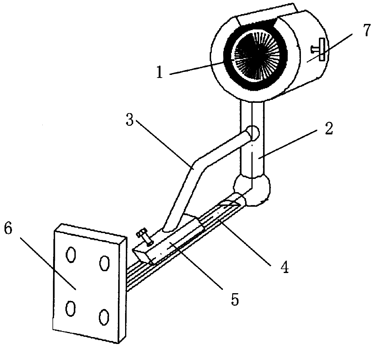
[0017] Such as figure 1 A device capable of cleaning up drilling swarf is shown, including an inner ring brush 1, a fixed bracket 2, a connecting rod 3, a slideway 4, a slider 5 and a base 6;

[0018] The fixed bracket 2 is L-shaped, with an open cylindrical mounting groove 7 at one end, and the other end is fixed on the base 6 by welding;

[0019] The inner ring brush 1 is composed of a cylindrical shell and a wire;

[0020] The metal wires are radially arranged in the casing;

[0021] Place the inner ring brush 1 in the installation groove 7 and fix it with screws;

[0022] The fixed bracket 2 is provided with a slideway 4;

[0023] One end of the connecting rod 3 is connected to the fixed bracket 2, and the other end is connected to the slider 5 and fixed by screws;

[0024] The slider 5 is placed in the slideway 4; the adjustment of the angle of the fixed bracket 2 is realized by adjusting the position of the slider 5 on the slideway 4 to drive the connecting rod 3.

...


PUM


Abstract

The invention discloses a device capable of clearing away drilling winding scraps. The device comprises an inner ring brush, a fixed support, a connecting rod, a sliding way, a sliding block and a base. The fixed support is in an L shape, an opened cylinder barrel-shaped mounting groove is formed in one end of the fixed support, and the other end of the fixed support is fixed to the base through welding. The inner ring brush is composed of a cylindrical shell and metal wires, and the metal wires are arranged in the shell in a radial shape. The inner ring brush is arranged in the mounting groove and fixed through a screw. The sliding way is arranged on the fixed support. One end of the connecting rod is connected with the fixed support, and the other end of the connecting rod is connected to the sliding block and fixed through a screw. The sliding block is put in the sliding way. The position of the sliding block on the sliding way is adjusted to drive the connecting rod to adjust the angle of the fixed support. According to the device, iron scraps are cleared away automatically and periodically in the numerical control continuous drilling process, the drilling continuity is improved, the machining efficiency is improved, and the labor intensity is reduced.

Description

technical field [0001] The invention relates to the technical field of mechanical processing, in particular to a device capable of cleaning up drilling swarf. Background technique [0002] Many parts of aero-engines need to be drilled, and the openness of the processed parts is very poor. The different materials of the parts and the openness of the drilling part lead to a large difference in the chip breaking performance of the iron filings during drilling. At present, the drilling of aero-engine parts is mostly processed by CNC machine tools, mainly to improve the processing accuracy and efficiency of parts. This requires that the entire processing process is continuous, the machine door is locked tightly, and the human intervention process should be as little as possible. However, since most CNC equipment does not have the function of high-pressure chip breaking, and there is no method to effectively avoid iron filings winding and automatic cleaning of iron filings in th...

Claims


Application Information

Patent Timeline
Patent Type & Authority Applications(China)
IPC IPC(8): B23B47/34
Inventor 张印郭艳华邓昶李振瑜范程程
Owner SHENYANG LIMING AERO-ENGINE GROUP CORPORATION
Learn More