
Tube electrode electroslag welding mould device applicable to steel rails

A technology for welding molds and molds, applied in the direction of rails, auxiliary devices, welding equipment, etc., can solve the problems of large space, position deviation, difficult grinding, etc., to achieve the effect of convenient assembly and fixation, improve work efficiency, and reduce production costs.

Pending Publication Date: 2018-04-20
METALS & CHEM RES INST CHINA ACAD OF RAILWAY SCI +2
View PDF9 Cites 3 Cited by
  • Summary
  • Abstract
  • Description
  • Claims
  • Application Information

AI Technical Summary

Problems solved by technology

When using multi-wire welding and electroslag welding, the wire feeding over a certain distance is prone to position deviation. If the feeding speed is not well controlled, the welding wire will catch fire with other positions on the end face of the rail, and it is difficult to ensure that it will always be in an arc-free state later.
The transition part between the rail head and the rail bottom in the shape of the weld seam occupies a large space, which is difficult to polish and is not convenient for seamless line construction

Method used


Image

  • Tube electrode electroslag welding mould device applicable to steel rails
  • Tube electrode electroslag welding mould device applicable to steel rails
  • Tube electrode electroslag welding mould device applicable to steel rails

Examples


Embodiment Construction

[0023] A pipe electrode electroslag welding mold device suitable for rails provided by the present invention will be described in detail below with reference to the accompanying drawings and specific embodiments.

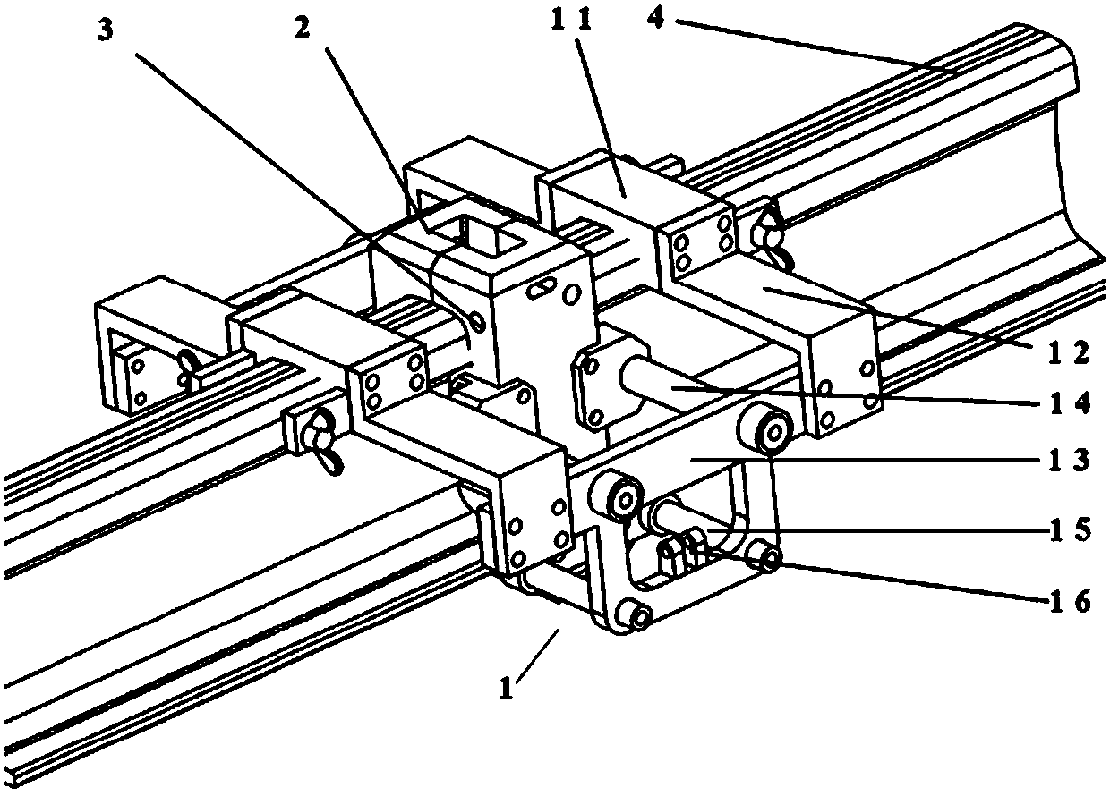
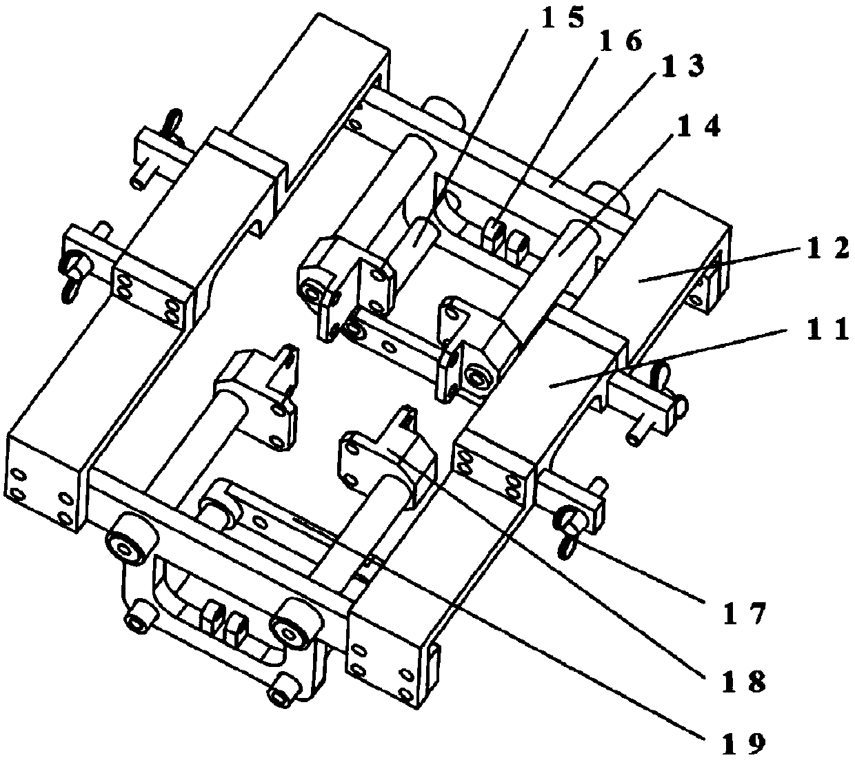
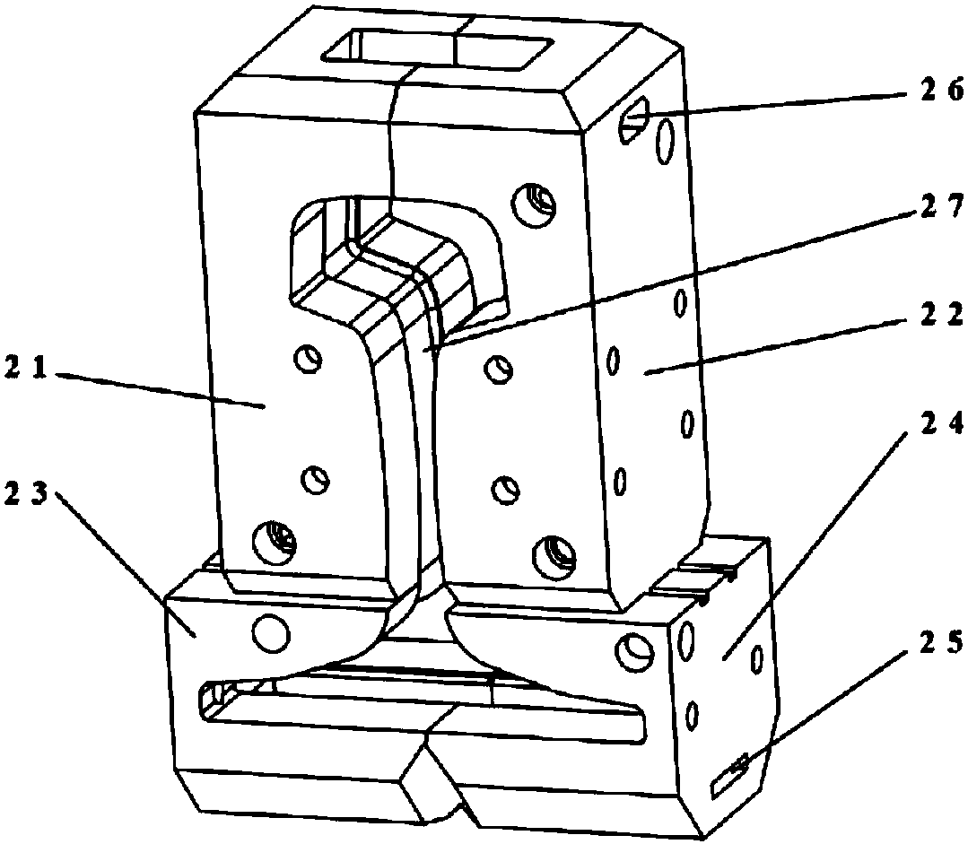
[0024] figure 1 with figure 2 It shows that a tube electrode electroslag welding mold device suitable for rails includes a mold fixing assembly assembly 1, a mold assembly 2 and a cooling cycle assembly 3, and is characterized in that the mold fixing assembly assembly 1 is fixed on On the rail head of the rail 4 to be welded, the mold assembly 2 is arranged in the middle of the mold fixing assembly assembly 1 , and the cooling circulation assembly 3 is arranged inside the mold assembly 2 .

[0025] Mold fixing assembly assembly 1 includes two rail head holding cards 11, four Z-shaped connecting plates 12, two rail waist and rail bottom mold sliding rod fixing support plates 13, four rail waist mold fixing sliding rods 14, and four rail bottom molds The fixed slid...


PUM


Abstract

The invention provides a tube electrode electroslag welding mould device applicable to steel rails. The tube electrode electroslag welding mould device comprises a mould fixing assembly (1), a mould assembly (2) and a cooling circulation assembly (3), and is characterized in that the mould fixing assembly (1) is fixed on a rail head of a to-be-welded steel rail (4); the mould assembly (2) is arranged on the middle part of the mould fixing assembly (1); and the cooling circulation assembly (3) is arranged in the mould assembly (2). The equipment is mainly a copper mould which is approximate toan I-steel shape, can be opened and closed simply and conveniently, can be used repeatedly, is convenient to assemble and fix and can realize water circular cooling; one-step continuous welding moulding of a steel rail whole section can be realized; the tube electrode electroslag welding mould device can be used for high-speed railways, interurban railways, subways, workshop gantry crane rails andthe like; the tube electrode electroslag welding mould device can be used flexibly; production cost is lowered; and working efficiency is improved.

Description

technical field [0001] The invention relates to the field of rail welding, in particular to a pipe electrode electroslag welding mold device suitable for rails. Background technique [0002] Electroslag welding has fast speed and high efficiency. The cooling speed of the weld seam is faster than that of aluminothermic welding and slower than that of arc welding, and the quality of the weld seam is easier to control. Electroslag welding is usually carried out when the weldment is in a vertical position. The slag pool not only needs sufficient depth, but also needs a certain volume. It is more suitable for the large-section welding of rails, but the rail feet of the rails are thinner and wider. It is the difficult position of electroslag welding. [0003] The key to rail electroslag welding mainly includes three parts: welding mold, welding material and welding process. The design of the welding mold needs to consider several aspects: mold material, cross-sectional shape of ...

Claims


Application Information

Patent Timeline
Patent Type & Authority Applications(China)
IPC IPC(8): B23K25/00B23K37/04
CPCB23K25/00B23K37/003B23K37/0443B23K2101/26B23K2103/04
Inventor 李金华彭鹏李力丁韦宋宏图高振坤胡玉堂赵国
Owner METALS & CHEM RES INST CHINA ACAD OF RAILWAY SCI
Learn More