
Hydraulic pin pulling device and pin pulling method adopting same

A hydraulic and hydraulic cylinder technology, which is applied in the field of support pin disintegration, can solve the problems that the machine cannot be repaired in time, the pin is easy to bounce, swing, and industrial accidents are easy to occur, so as to improve the pin removal effect and labor efficiency , Put an end to the effect of pulling out the pin and breaking the chain, saving manpower

Pending Publication Date: 2018-04-20
HUAINAN MINING IND GRP
View PDF6 Cites 4 Cited by
  • Summary
  • Abstract
  • Description
  • Claims
  • Application Information

AI Technical Summary

Problems solved by technology

If the position of disassembly changes, it needs to be repaired again, which is a waste of manpower and material resources, and when using a hoist to operate, the hoist used to pull out the pin shaft is a 5t hoist, and the traction force is small
When the pressure on the pin shaft is high, many people are required to cooperate to operate the hoist. After the pin shaft is pulled out, it is easy to bounce and swing. are limited by space
Often due to these reasons, because a pin cannot be pulled out, the machine cannot be repaired in time, which ultimately affects the production

Method used


Image

  • Hydraulic pin pulling device and pin pulling method adopting same
  • Hydraulic pin pulling device and pin pulling method adopting same
  • Hydraulic pin pulling device and pin pulling method adopting same

Examples


Embodiment Construction

[0027] Specific embodiments of the present invention will be described in detail below in conjunction with the accompanying drawings. It should be understood that the specific embodiments described here are only used to illustrate and explain the present invention, and are not intended to limit the present invention.

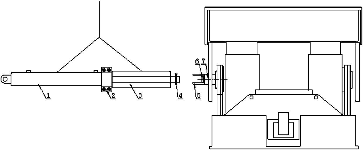
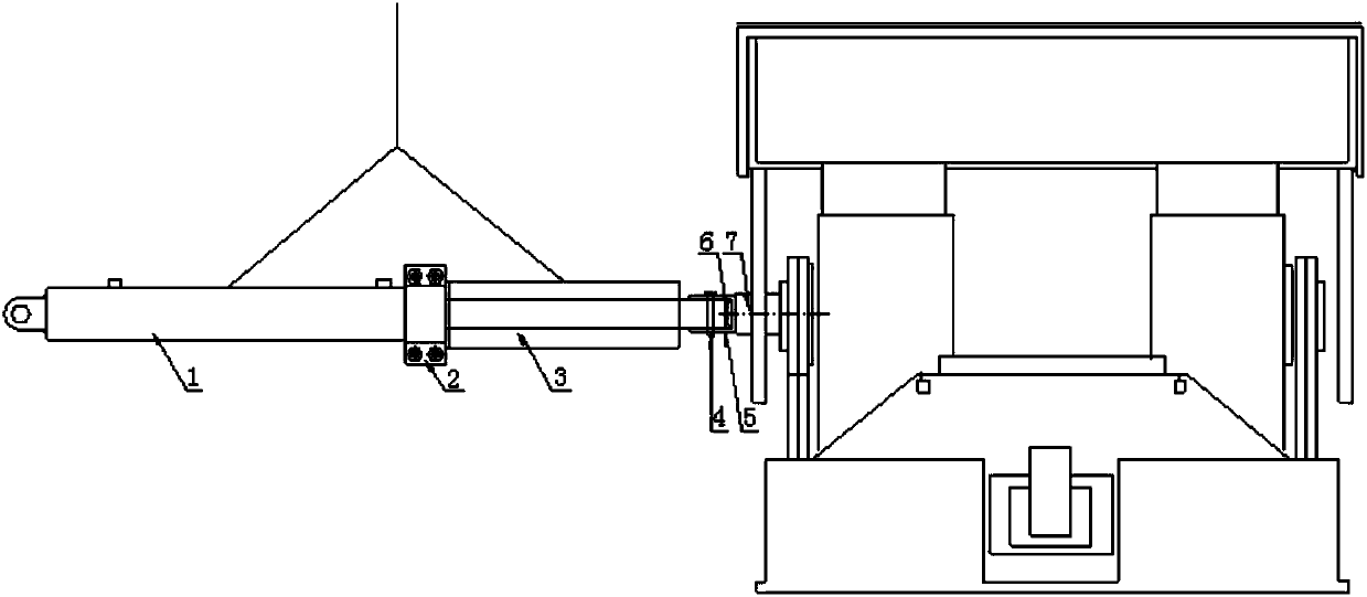
[0028] like figure 1 As shown, a hydraulic pin pulling device provided by the present invention adopts hydraulic pressure as a power source, and includes a jack 1, a hoop 2, a sleeve 3, a pin pulling bolt 4, a connecting head 5, a jack pin shaft 6 and a hydraulically operated valve.

[0029] The jack 1 is connected to the sleeve 3 through the hoop 2, and the sleeve 3 is set outside the jack 1.

[0030] The pin puller bolt 4 is fixed on the pin shaft 7 of the hydraulic support after passing through the hole in the middle of the connector 5 .

[0031] The connecting head 5 is fixed on the front end of the hydraulic cylinder pushed out by the jack 1 through the j...


PUM


Abstract

The invention discloses a hydraulic support pin shaft pull-out device. The hydraulic support pin shaft pull-out device comprises a jack, a hoop, a sleeve, a pin pulling bolt, a connecting head, a jackpin shaft and a hydraulic operating valve. The jack is connected with the sleeve through the hoop, and the jack is sleeved with the sleeve; the pin pulling bolt passes through a middle hole of the connection head, and then is fixed to a hydraulic support pin shaft; and the connection head is fixed to the front end of a hydraulic cylinder pushed out by the jack through the jack pin shaft. The hydraulic pin pulling device (the hydraulic support pin shaft pull-out device) is fixed to a top plate through a coir rope or a hoist chain; and by adjusting the chain length, the position and the heightof the hydraulic pin pulling device are determined. The invention discloses a method for adopting the hydraulic support pin shaft pull-out device for performing hydraulic support disassembling. The hydraulic support pin shaft pull-out device has the beneficial effects that due to the use of the hydraulic pin pulling device, the safety coefficient of personnel in the pin pulling process is increased, the construction links are reduced, the labor intensity of a worker is greatly reduced, and the pin pulling effect and the labor efficiency are improved.

Description

technical field [0001] The invention relates to the disintegration of a support pin during the dismantling of fully mechanized mining face equipment, in particular to a hydraulic pin pulling device and a pin pulling method using the device. technical background [0002] In recent years, mining companies have actively promoted the transformation of production methods, and a series of new equipment such as hydraulic lifting frames have been put into use, which has played an important role in improving production efficiency. "If a worker wants to be good at his work, he must first sharpen his tools." Every progress in the installation and dismantling of fully mechanized mining face equipment is accompanied by the replacement of equipment, which is more conducive to safe production, conducive to reducing manpower and improving efficiency, and is conducive to reducing labor costs. Labor intensity. [0003] In mine machinery, pin shafts are used for connection in many occasions, ...

Claims


Application Information

Patent Timeline
Patent Type & Authority Applications(China)
IPC IPC(8): B25B27/02
CPCB25B27/026
Inventor 王冰燕洪伟章文峰刘会静孙西峰彭培李昶昶吴灿
Owner HUAINAN MINING IND GRP
Learn More