
Defoaming Tray Mold Mechanism

A mold mechanism and tray technology, which is applied in the field of injection molding, can solve the problems of bubbles in the stock solution and uneven flow velocity, and achieve the effect of reducing bubbles and uniform flow velocity

Active Publication Date: 2019-09-03
重庆市魏来雄鑫橡塑制品有限责任公司
View PDF1 Cites 0 Cited by
  • Summary
  • Abstract
  • Description
  • Claims
  • Application Information

AI Technical Summary

Problems solved by technology

[0010] The present invention intends to provide a defoaming tray mold mechanism to solve the problems of uneven flow velocity and bubbles in the stock solution in the prior art when the stock solution of injection molding flows through the feed plate

Method used


Image

  • Defoaming Tray Mold Mechanism
  • Defoaming Tray Mold Mechanism
  • Defoaming Tray Mold Mechanism

Examples


Embodiment Construction

[0035] The present invention will be described in further detail below by means of specific embodiments:

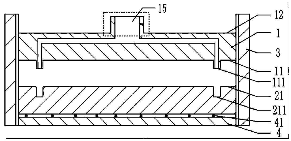
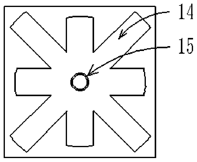
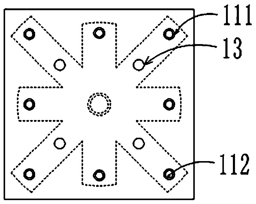
[0036] The reference signs in the drawings of the description include: fixed mold 1, movable mold 2, fixed mold working surface 11, fixed mold injection surface 12, movable mold working surface 21, protruding part 111, protruding gate 112, common gate 13. Recess 211 , feed plate 14 , tubular injection port 15 , slot 16 , reed 17 , limit block 18 , blocking block 19 , limit plate 3 , support plate 4 , and spring 41 .

[0037] Embodiment is shown in accompanying drawing basically:

[0038] The mold mechanism of the defoaming tray of this program includes a support part and a mold part;

[0039] Such as figure 1 , Figure 5 and Figure 6 As shown, the mold part includes a movable mold 2, a fixed mold 1, a reed 17 and a blocking block 19. The upper end surface of the fixed mold 1 is the injection molding surface of the fixed mold, the lower end surface of the fixed mold 1...


PUM


Abstract

The invention discloses a defoaming tray die mechanism, and belongs to the technical field of injection forming. The following solution is provided for solving the problems that in the prior art, whena fusion stock solution flows through a feeding plate, the flow speed is not uniform, and bubbles exist in the fusion stock solution. In the scheme, a die part and a supporting part are included. Thedie part comprises a movable die and a fixed die. The movable die comprises a movable die work face and a movable die supporting face. The fixed die comprises a fixed die work face and a fixed die injection molding face. A plurality of pouring gates are arranged on the fixed die work face. After the fixed die work face coincides with the movable die work face, a die cavity is formed. The fixed die injection molding face is provided with a feeding frame communicating with the pouring gates. The feeding frame is provided with a tubular injection molding port, a clamping groove is formed in theside wall of the tubular injection molding port, a reed is arranged in the clamping groove, and the length of the part, stretching into the tubular injection molding port, of the reed is smaller thanthe diameter of the inner wall of the tubular injection molding port. The supporting part comprises limiting plates arranged on the two sides of the die part and a supporting plate arranged below themovable die supporting face. The supporting plate is evenly provided with springs, and the other ends of the springs are connected with the movable die supporting face.

Description

technical field [0001] The invention belongs to the technical field of injection molding. Background technique [0002] Injection mold is a tool for producing plastic products, usually consisting of a moving mold and a fixed mold. During production, the mold is installed in the injection molding machine, and the plastic that is heated and melted is injected into the cavity of the injection mold by high pressure using the injection molding machine. The mechanism is used to push out to complete an injection molding. [0003] When injecting trays, the current mold usually has multiple gates on the surface of the fixed template, and high-pressure injection molding is used to complete the injection molding process of the tray. There are many feet on the tray, and because the feet are usually located on the edge of the tray, during the injection molding process, the plastic often cannot fill the mold cavity at the feet, so that the thickness of the feet is not enough. If the inj...

Claims


Application Information

Patent Timeline
Patent Type & Authority Patents(China)
IPC IPC(8): B29C45/26B29C45/27B29C45/17
Inventor 熊强
Owner 重庆市魏来雄鑫橡塑制品有限责任公司
Learn More