
A touchpad lamination device

A technology for laminating equipment and touch panels, applied in the directions of lamination auxiliary operations, chemical instruments and methods, lamination, etc., can solve the problems of damage to circuit boards, waste of manpower, uneven strength, etc., to achieve accurate positioning and improve work efficiency. Effect

Active Publication Date: 2019-07-02
重庆市川仁精密机械有限公司
View PDF4 Cites 1 Cited by
  • Summary
  • Abstract
  • Description
  • Claims
  • Application Information

AI Technical Summary

Problems solved by technology

[0002] Notebook touchpads are composed of a touch circuit board and a glass plate when they are assembled. The initial manufacturer sticks a layer of protective adhesive on the back of the circuit board. During assembly and production, the adhesive had to be torn off. The form of tearing off the adhesive is a great waste of manpower, and because the strength is unavoidable when people tear it, it may even quickly tear off the adhesive and damage the circuit board; and the bonding of the glass plate and the touch circuit board requires Highly precise press-fitting requires appropriate strength to ensure that components will not be damaged due to excessive pressure, and there will be no air bubbles between the glass plate and the circuit board due to too small pressure; at the same time, due to the notebook production has Strong seasonality, within a short construction period, the past equipment lamination speed cannot meet the needs of mass and rapid production

Method used


Image

  • A touchpad lamination device
  • A touchpad lamination device
  • A touchpad lamination device

Examples


Embodiment Construction

[0024] The present invention will be further described below in conjunction with the accompanying drawings and specific embodiments, so that those skilled in the art can better understand the present invention and implement it, but the examples given are not intended to limit the present invention.

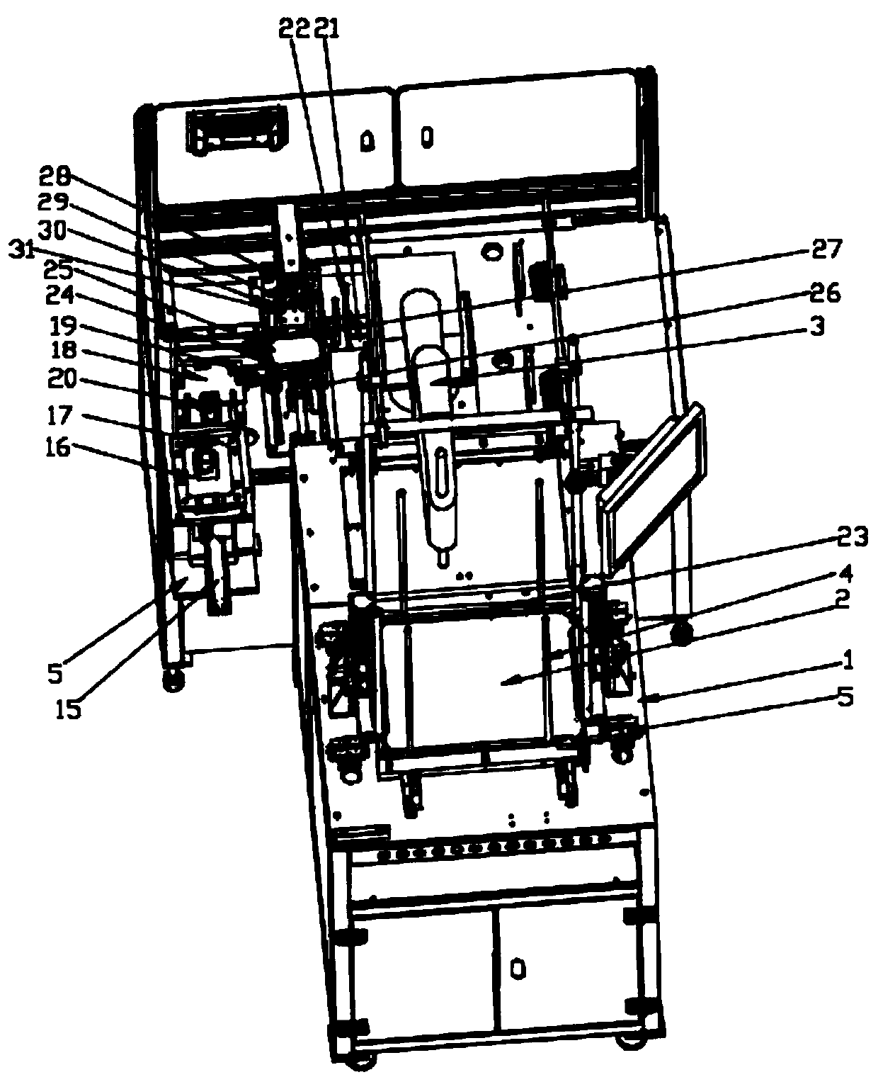
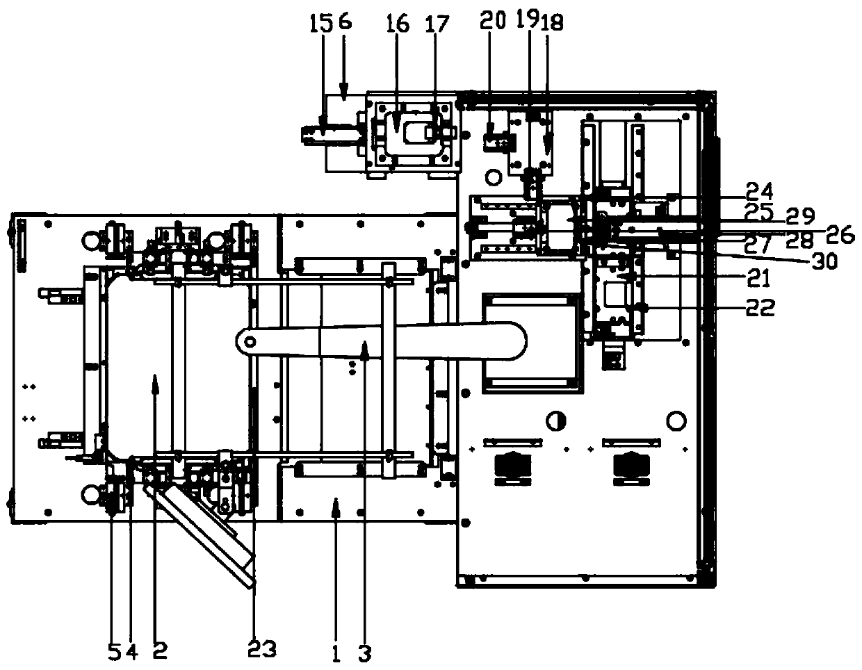
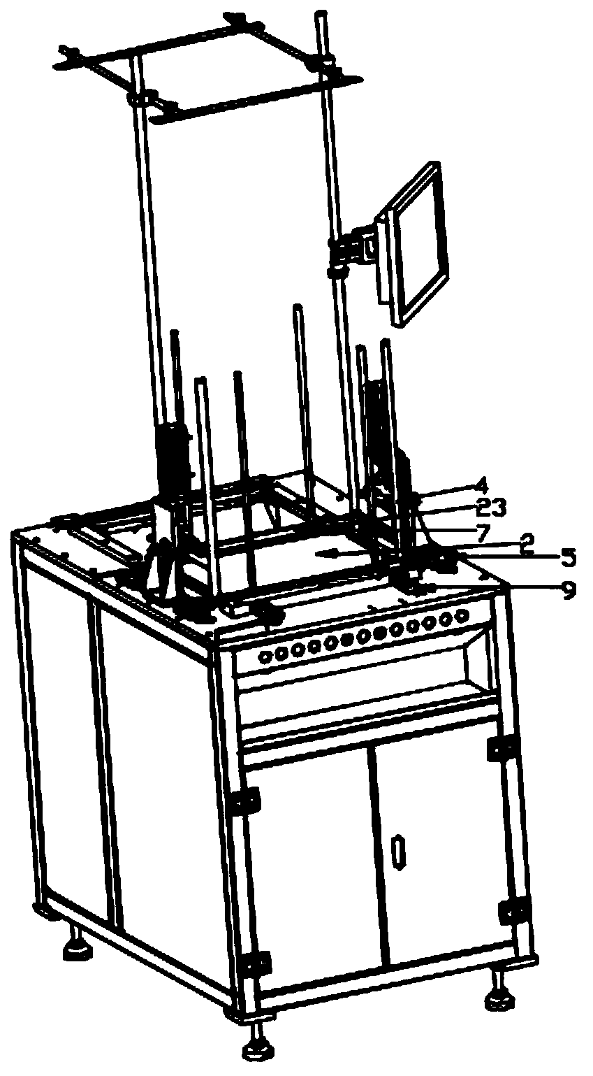
[0025] 1. Combining with figure 1 , a touch panel laminating equipment, comprising an operation platform 1, a circuit board feeding station on the operation platform, an iron key feeding station, a glass plate sticking station and an iron key pressing station; Both the material station and the iron key feeding station include a material storage stereotyped plate 2 and a mechanical arm 3, and the described material storage stereotyped plate 2 is provided with a positioning column 4, an adjusting cylinder 5 arranged on the four corners of the stock material stereotyped plate and for Push the circuit board from the guide seam 7 to slide away from the push mechanism of the storage and...


PUM


Abstract

The invention relates to the technical field of laptop assembling equipment, and in particular relates to a laminating device for a touchpad. The device comprises an operation platform, a circuit board charging station, an iron key charging station, a glass board adhering station and an iron key laminating station, wherein the circuit board charging station, the iron key charging station, the glass board adhering station and the iron key laminating station are arranged on the operation platform; each of the circuit board charging station and the iron key charging station comprises a storing sizing board and a mechanical arm; positioning vertical columns are arranged around the storing sizing plate; adjusting cylinders are arranged on four corners of the storing sizing plate; a pushing mechanism for pushing a circuit board to slide away the storing sizing plate from a guide seam is provided; the glass board adhering station comprises a glass board positioning plate and a limiting column; the iron key laminating station is positioned between the glass board adhering station and the iron key charging station; the iron key laminating station comprises a conveying slide rail; a loadingplate is arranged on the slide rail; a positioning plate is arranged on the loading plate; a pressure stabilizing cylinder is correspondingly arranged above the conveying slide rail. The device is high in accuracy, automatic to tear back gum, and automatic and accurate to laminate, and meets the demand of massive and quick production.

Description

technical field [0001] The invention relates to the technical field of notebook assembling equipment, in particular to a touchpad bonding equipment. Background technique [0002] Notebook touchpads are composed of a touch circuit board and a glass plate when they are assembled. The initial manufacturer sticks a layer of protective adhesive on the back of the circuit board. During assembly and production, the adhesive had to be torn off. The form of tearing off the adhesive is a great waste of manpower, and because the strength is unavoidable when people tear it, it may even quickly tear off the adhesive and damage the circuit board; and the bonding of the glass plate and the touch circuit board requires Highly precise press-fitting requires appropriate strength to ensure that components will not be damaged due to excessive pressure, and there will be no air bubbles between the glass plate and the circuit board due to too small pressure; at the same time, due to the notebook ...

Claims


Application Information

Patent Timeline
Patent Type & Authority Patents(China)
IPC IPC(8): B32B37/10B32B38/10B32B38/18
CPCB32B37/10B32B38/10B32B38/1833B32B38/1841
Inventor 杨勇明
Owner 重庆市川仁精密机械有限公司
Learn More