Check patentability & draft patents in minutes with Patsnap Eureka AI!

High-strength light rotation device

A rotating device, high-strength technology, used in seat arrangement, transportation and packaging, aircraft parts, etc., can solve the problems of low bearing performance and heavy weight, and achieve the effect of reducing weight, simple structure, and eliminating gaps

Pending Publication Date: 2018-04-20
AEROSPACE LIFE SUPPORT IND LTD
View PDF6 Cites 5 Cited by
  • Summary
  • Abstract
  • Description
  • Claims
  • Application Information

AI Technical Summary

Problems solved by technology

[0004] Purpose of the invention: In order to overcome the problems of low load-bearing performance and heavy weight of the existing rotating device, the present invention provides a high-strength and light-weight rotating device, which can effectively solve the problems of strength performance and weight, and has a simple structure and easy installation

Method used


Image

  • High-strength light rotation device
  • High-strength light rotation device
  • High-strength light rotation device

Examples


example 1

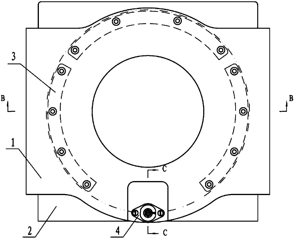
[0020] The rotating device of the present invention includes an upper body 1, a lower body 2, an engaging plate 3, a base 4, a locking pin 5, an upper slide 6, a slide 7, a steel ball 8, a cage 9, a pull ring 10, a compression spring 11, Blocking cover 12, the upper body 1 is connected with the structure that needs to be rotated; the lower body 2 is connected with the product fixing structure, and can also be directly connected with the aircraft floor or bulkhead; the lower end of the upper body 1 and The upper end of the engagement plate 3 is fixedly connected, the lower end of the upper body 1 is fixedly connected with the upper slideway 6 to form a hemispherical slideway 101, and the upper end of the lower body 2 is fixedly connected with the glideway 7 to form a hemispherical slideway 102. The ball 8 is fixed between the upper slideway 6 and the slideway 7 through the round hole 103 of the cage 9, and the "hook" structure 104 of the engaging plate 3 engages in the annular g...

example 2

[0022] The rotating device of the present invention includes an upper body 1, a lower body 2, an engaging plate 3, a base 4, a locking pin 5, an upper slide 6, a slide 7, a steel ball 8, a cage 9, a pull ring 10, a compression spring 11, Blocking cover 12, the upper body 1 is connected with the structure that needs to be rotated; the lower body 2 is connected with the product fixing structure, and can also be directly connected with the aircraft floor or bulkhead; the lower end of the upper body 1 and The upper end of the engaging plate 3 is fixedly connected, the lower end of the upper body 1 is fixedly connected with the upper slideway 6, the upper end of the lower body 2 is fixedly connected with the slideway 7, and the steel ball 8 is fixed on the upper slideway 6 through the round hole 103 of the cage 9 In the middle of the glideway 7, the "hook" structure 104 of the engaging plate 3 engages in the annular groove 105 of the lower body 2 to play the role of rotating guide a...


PUM


Abstract

The invention relates to a rotation device, in particular to a high-strength light rotation device required to bear the large load and to be low in weight. According to structural features, the strength performance and the weight index of a product, the shapes and sizes of an upper body and a lower body can be freely designed, a connecting piece connected with the rotation device is omitted, and the weight is effectively reduced. A hook-shaped structure of an engagement board is engaged with an annular groove structure of the lower body, a rotation guide effect is achieved, a gap generated inrotation is eliminated, the large load can be transmitted, and the problem that a common rotation device cannot bear the large radial load is effectively solved. A locking pin on the upper body is inserted in a locking hole of the lower body, so that the stability of a product structure is guaranteed, meanwhile the position of the locking hole can be determined according to actual requirements, and a locking function at different rotation angles can be achieved. The rotation device is simple in structure, convenient to install, free of limitation of the installation position and the size and high in reliability.

Description

technical field [0001] The invention relates to a rotating device, in particular to a high-strength and light-weight rotating device that needs to withstand high overload and requires light weight. Background technique [0002] The modern aviation industry has higher and higher expectations for the flight performance of aircraft, and pays more and more attention to the safety of crew members. The seat is an essential airborne equipment on the aircraft. Its main purpose is to provide a comfortable seating and use environment for the crew, and to protect the occupants from damage as a force transmission terminal in an aircraft crash environment. Therefore, the current aircraft overall unit has higher and higher requirements for the strength performance and weight index of the seat. [0003] Due to the cabin layout and use requirements, some seats on the aircraft need to have a rotary adjustment function. Domestic swivel seats basically use thrust ball bearings, steel ball sl...

Claims


Application Information

Patent Timeline
IPC IPC(8): B64D11/06
CPCB64D11/0639Y02T50/40
Inventor 朱鹏黄春丽孟凡辉吴照江程玺张鑫李悦
Owner AEROSPACE LIFE SUPPORT IND LTD
Features
  • R&D
  • Intellectual Property
  • Life Sciences
  • Materials
  • Tech Scout
  • Unparalleled Data Quality
  • Higher Quality Content
  • 60% Fewer Hallucinations
Learn More