Full-automatic packing method

A fully automatic packaging and bagging technology, used in packaging, transportation packaging, transportation and packaging, etc., can solve the problems of falling food materials, equipment failure, inaccurate positioning, etc., and achieve improved packaging efficiency and stable operation. Effect

Inactive Publication Date: 2018-04-20
广东邦天智能制造有限公司
8 Cites 21 Cited by

AI-Extracted Technical Summary

Problems solved by technology

Existing packaging machines are generally divided into rotary packaging machines and linear transmission packaging machines. Among them, the packaging method used by the rotary packaging machine is to set a plurality of claws on the rotary table, and the claws hold the packaging bag along the The circle moves to each processing position in turn, which is prone to the problems of alignment errors between the turntabl...

Method used

Specifically, the packaging bag supply device 100 includes a first mounting base 110 and a bag-taking mechanism 130, and the two ends of the first mounting base 110 are respectively provided with mutually symmetrical packaging bag supply racks 120, the There is at least one storage bag groove 121 on the packaging bag supply rack 120, which is used to place a plurality of vertically arranged sheet-shaped packaging bags 10 in the storage bag groove 121, and the inner end of the storage bag groove 121 is provided with a The bag-taking mouth 122 of the packaging bag is provided with a push mechanism 123 for pushing a plurality of said packaging bags toward the bag-taking mouth 122 at the outer end; They are arranged closely together along the direction of the storage bag groove 121 , and the packaging bags arranged on the innermost side are held against and fixed on the bag taking port 122 . In thi...

Abstract

The invention discloses a full-automatic packing method. The full-automatic packing method comprises the following steps: a bag taking sucker of a bag taking mechanism sucks packing bags to position on a bag taking station; a conveying and clamping mechanism clamps the packing bags from the bag taking station, and transversely clamps and conveys the packing bags to a bag opening station; the conveying and clamping mechanism transversely clamps and shifts the packing bags from the bag opening station to a filling station in a bag opening state; a filling and unloading device fills the packing bags in the filling station; after filling is finished, the packing bags are transversely clamped and shifted to a transfer station from the filling station by the conveying and clamping mechanism; thetransfer mechanism clamps the packing bags from the transfer station, and shifts the packing bags into a vacuum cavity of a vacuumizing and sealing device for fixation; and the vacuumizing and sealing device hot seals the upper ends of the packing bags by a hot sealing module after vacuumizing of the packing bags through the vacuum cavity. The packing method is stable in operation, can effectively prevent equipment failures caused by splashing of food materials outside the bags, and greatly improves the packing efficiency.

Application Domain

Technology Topic

Image

  • Full-automatic packing method
  • Full-automatic packing method
  • Full-automatic packing method

Examples

  • Experimental program(1)

Example Embodiment

[0041] Embodiments of the present invention are described in detail below, examples of which are shown in the drawings, wherein the same or similar reference numerals designate the same or similar elements or elements having the same or similar functions throughout. The embodiments described below by referring to the accompanying drawings are exemplary and are intended to explain the present invention, but cannot be construed as limitations to the present invention. Based on the embodiments in the present invention, those skilled in the art do not make creative work All other embodiments obtained below all belong to the protection scope of the present invention.
[0042] In describing the present invention, it is to be understood that the terms "center", "longitudinal", "transverse", "length", "width", "thickness", "upper", "lower", "front", " Back", "Left", "Right", "Vertical", "Horizontal", "Top", "Bottom", "Inner", "Outer", "Clockwise", "Counterclockwise", "Axial", " The orientation or positional relationship indicated by "circumferential", "radial", etc. is based on the orientation or positional relationship shown in the drawings, and is only for the convenience of describing the present invention and simplifying the description, rather than indicating or implying that the referred device or element must Having a particular orientation, being constructed and operating in a particular orientation, and therefore not to be construed as limiting the invention.
[0043] In addition, the terms "first" and "second" are used for descriptive purposes only, and cannot be interpreted as indicating or implying relative importance or implicitly specifying the quantity of indicated technical features. Thus, a feature defined as "first" and "second" may explicitly or implicitly include one or more of these features. In the description of the present invention, "plurality" means two or more, unless otherwise specifically defined.
[0044] In the present invention, unless otherwise clearly specified and limited, terms such as "installation", "connection", "connection" and "fixation" should be understood in a broad sense, for example, it can be a fixed connection or a detachable connection , or integrally connected; may be mechanically connected, may also be electrically connected; may be directly connected, may also be indirectly connected through an intermediary, and may be internal communication between two components. Those of ordinary skill in the art can understand the specific meanings of the above terms in the present invention according to specific situations.
[0045] In the present invention, unless otherwise clearly specified and limited, a first feature being "on" or "under" a second feature may include direct contact between the first and second features, and may also include the first and second features Not in direct contact but through another characteristic contact between them. Moreover, "above", "above" and "above" the first feature on the second feature include that the first feature is directly above and obliquely above the second feature, or simply means that the first feature is horizontally higher than the second feature. "Below", "beneath" and "under" the first feature to the second feature include that the first feature is directly below and obliquely below the second feature, or simply means that the first feature has a lower level than the second feature.
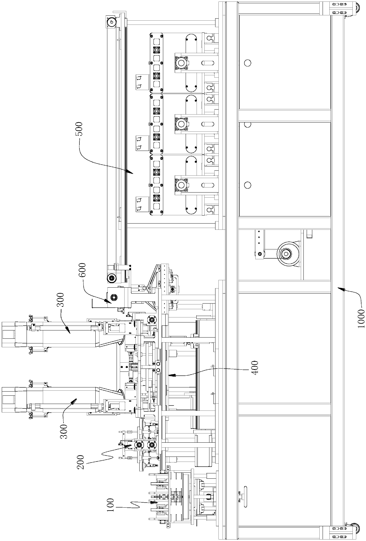
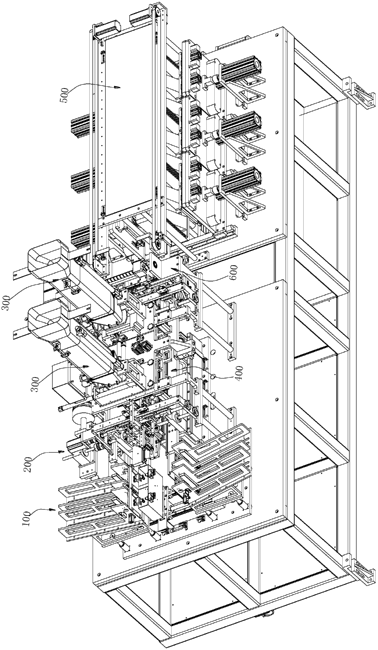
[0046] The fully automatic packaging method of the embodiment of the present invention will be described in detail below with reference to the accompanying drawings. The accompanying drawing is a schematic diagram of a packaging machine using the fully automatic packaging method, which is a packaging machine that performs various treatments on two packaging bags at a time, but the following descriptions can also be applied to one, three or one bag at a time. Packing machine for various processing of four bags.
[0047] like Figure 1 to Figure 3 as well as Figure 5 to Figure 20As shown, the fully automatic packaging machine includes a frame 1000, a packaging bag supply device 100, a bag opening device 200, a filling and unloading device 300, a grabbing and conveying device 400, and a vacuum sealing device 500. The packaging bag supply device 100, the bag opening device 200, the filling and unloading device 300 and the vacuum sealing device 500 are sequentially arranged on the frame 1000 along the transverse direction; the packaging bag supply device 100 includes a packaging bag supply rack 120 and is used for The bag-taking mechanism 130 that absorbs the packaging bag in the packaging bag supply rack 120; the grasping and conveying device 400 is sequentially installed under the bag-opening device 200 and the filling and unloading device 300, for the bag-taking mechanism The package bag sucked by 130 is clamped and delivered to the bag opening mechanism 200 for opening, and the package bag after opening is clamped and delivered to the filling and unloading device 300 for filling.
[0048] combine image 3 and Figure 4 Shown, according to the fully automatic packaging method of the embodiment of the present invention, comprises steps:
[0049] Take the bag, the bag taking suction nozzle 133 of the bag taking mechanism 130 sucks a packaging bag 10a in a vertical state to make it located on the bag taking station 20, the packaging bag 10a has a sack end positioned at the upper end and a closed closure positioned at the lower end. end and side walls.
[0050] To open the bag, the transmission clamping mechanism 420 clamps the packaging bag 10a from the bag taking station 20 and clamps and transmits it to the bag opening station 30 in the lateral direction. The two bag opening suction nozzles 215 of the bag opening device 200 Adsorb the two side walls of the packaging bag 10b in the bag opening station 30 respectively, and make the two bag opening suction nozzles 215 away from each other to open the mouth of the packaging bag 10b.
[0051] Filling, the conveying clamping mechanism 420 moves the packaging bag 10b from the bag opening station 30 to the filling station 40 in a horizontal direction while maintaining its open bag state, and is clamped by the fixed clamping mechanism 410, The filling and unloading device 300 fills the packaging bag 10c of the filling station 40, and after the filling is completed, the transfer clamping mechanism 420 is clamped and moved from the filling station 40 to the transfer station along the horizontal direction. bit 50.
[0052] Vacuum sealing, the conveying mechanism 540 clamps the packaging bag 10d from the transfer station 50 and moves it to the vacuum cavity of the vacuum sealing device 500 for fixing, and the vacuum sealing device 500 vacuumizes the packaging bag 10e through the vacuum cavity The upper end of the packaging bag 10e is heat-sealed by the heat-sealing assembly.
[0053] Further, the bag taking station 20, bag opening station 30, filling station 40 and switching station 50 are all on the same horizontal horizontal line. That is to say, the packaging bag 10 is moved to the bag taking station 20, the bag opening station 30, the filling station 40 and the transfer station sequentially along the horizontal line under the action of the conveying clamping mechanism 420 of the grabbing conveying device 400. 50 on.
[0054] Specifically, the packaging bag supply device 100 includes a first installation base 110 and a bag taking mechanism 130, and two ends of the first installation base 110 are respectively provided with mutually symmetrical packaging bag supply racks 120, and the packaging bag supply There is at least one storage bag groove 121 on the frame 120, which is used to place a plurality of vertically arranged sheet-shaped packaging bags 10 in the storage bag groove 121, and the inner end of the storage bag groove 121 is provided with a wall smaller than the packaging bag. Take the bag mouth 122, the outer end is provided with and is used for pushing a plurality of described packaging bags to the pushing mechanism 123 of described bag taking mouth 122 direction; The directions of the grooves 121 are closely arranged together, and the packaging bags arranged on the innermost side are held against and fixed on the bag-taking mouth 122 . In this way, the bag-taking mechanism 130 can respectively suck the packaging bag 10 from the two packaging bag supply racks 120 to the bag-taking station 20, and the movement stroke of the bag-taking mechanism 130 is reduced by the bidirectional suction design mechanism, which greatly improves the The bag-taking efficiency of bag-taking mechanism 130.
[0055] like Image 6 As shown, the bag opening device 200 includes a bag opening mechanism 210 and a holding mechanism 220 . Wherein, the bag opening mechanism 210 includes a gantry frame 211, a first longitudinal slide rail 212 arranged on the gantry frame 211, two suction nozzle mounting seats 213 slidably arranged on the first longitudinal slide rail 212, And the bag opening driving mechanism 214 that drives the relative movement of the two suction nozzle mounting seats 213, the two suction nozzle mounting seats 213 are arranged oppositely, and the relative inner side is provided with a relative bag opening suction nozzle 215, through the two suction nozzles The bag opening suction nozzle 215 on the mounting seat 213 pulls the sack of the packaging bag open. The holding mechanism 220 includes a clamping frame 221 fixed to the gantry frame 211 and located between the two suction nozzle mounts 213, fixedly connected to the clamping frame 221 and sliding along the first longitudinal direction. Two pneumatic fingers 222 arranged vertically at intervals in the direction of the rail 212, the distance between the two pneumatic fingers 222 is the width of the top of the packaging bag after opening, and are used to clamp and fix the positions at both ends of the top of the packaging bag, Thereby, the opening state of the packaging bag is maintained when clamping.
[0056] Further, the bag opening step also includes the step of blowing air into the opening of the packaging bag to expand the inside of the packaging bag. Specifically, the clamping frame 221 is provided with an air jet tube 224, the lower end of the air jet tube 224 is an air outlet end, and extends between the two pneumatic fingers 222, and is located at the end of the bag opening station. above. In this way, when the bag opening mechanism 210 opens the packaging bag, the air outlet end of the gas injection pipe 224 will eject gas, so that the inside of the packaging bag will expand after opening the bag, so as to facilitate the filling of the packaging bag in the later stage, and avoid the failure of the packaging bag to open. completely.
[0057] like Figure 7 to Figure 10 As shown, the filling step also includes the step of opening the mouth of the bag so that the feeding tube 310 can extend into the mouth of the packaging bag for filling. Specifically, two filling and unloading devices 300 are arranged laterally on the frame 1000 of the packaging machine, and each filling and unloading device 300 includes a silo 340, a main body 330, a feeding pipe 310, and an auxiliary bag support mechanism. 350; the main body 330 has an accommodating chamber for receiving the material dropped from the silo 340; the feeding tube 310 is installed at the bottom of the main body 330 vertically and vertically, and is driven by the first lifting drive mechanism 360 Drive its lifting motion, and the upper end of described feeding tube 310 is communicated with described accommodating cavity; And the expansion bracket 352 installed on the pneumatic finger 351, the expansion bracket 352 includes two bag holders 3521 respectively fixed on the two grippers 3511 of the pneumatic finger 351, the two support Free ends of the pockets 3521 respectively extend to opposite sides of the feeding tube 310 , and extend downwards to form pockets 3522 . In this way, when the packaging bag moves to the filling station, the pneumatic finger 351 and the bag supporter 3521 can be driven downward through the second lifting mechanism, so that the bag supporter 3522 is located in the pocket of the packaging bag, and the pneumatic finger 351 can be used to move downwards. Drive the two bag supporting parts 3521 to drive the two bag supporting parts 3522 located in the bag mouth to expand each other to open the bag mouth of the packaging bag, and then the first lifting mechanism drives the feeding tube 310 to smoothly enter the opened bag mouth, It is convenient for unloading to ensure that there is no leakage during filling, especially when the filled material has oil, and the oil will stick to the mouth of the bag, resulting in incomplete sealing or splashing in the later stage, resulting in equipment failure.
[0058] like Figure 11 to Figure 14 As shown, the grasping and conveying device 400 includes a fixed clamping mechanism 410 and a conveying clamping mechanism 420 arranged on the frame 1000, and the fixed clamping mechanism 410 is located below the filling and unloading device. The conveying clamping mechanism 420 is located below the fixed clamping mechanism 410; wherein, the packaging bag supply device 100 and the bag opening device 200 of the packaging machine are sequentially arranged in front of the conveying clamping mechanism 420 along the transverse direction.
[0059] The fixed clamping mechanism 410 includes two fixed clamping frames 411 that can slide longitudinally, and a first drive mechanism 413 for driving the two fixed clamping frames 411 to move relative to each other. A pair of first chucks 412 for clamping the opened packaging bag are arranged on the opposite inner side of the rack 411 corresponding to the position below the feeding tube 310 of the filling and feeding device 300 . When the two fixed clamping frames 411 are close to each other so that the two first chucks 412 abut against each other, it is used to transfer the clamping mechanism 420 to the upper two ends of the opened bag packaging bag below the feeding tube 310. Hold and fix it so that the feeding pipe 310 descends and stretches into the pocket for filling.
[0060] The conveying clamping mechanism 420 includes two sliding clamping frames 421 that can slide relative to each other in the longitudinal direction and can slide in the transverse direction at the same time, a second driving mechanism 422 for driving the relative movement of the two sliding clamping frames 421 , and The third driving mechanism 423 for driving the two sliding clamping frames 421 to move laterally at the same time, the opposite inner sides of the two sliding clamping frames 421 are sequentially provided for clamping and transporting the packaging bags along the packaging bag conveying direction. At least one pair of second chucks 424 and at least one pair of third chucks 425, and the front ends of the two sliding clamping frames 421 are respectively connected with a clamping plate 426, the second chucks 424 and the first clamps The heads 412 are relative up and down.
[0061] Preferably, four pairs of first clamps 412 are distributed laterally on the inside of the two fixed clamping frames 411, and the distance between the first pair of first clamps 412a and the second pair of first clamps 412b is the same as that of the third pair of first clamps 412b. The distance between the first chuck 412c and the fourth pair of first chucks 412d is the same, and the first pair of first chucks 412a is located below the feeding pipe 310 of the first filling and unloading device 300, and the fourth pair of first The chuck 412d is located below the feeding pipe 310 of the second filling and unloading device 300; correspondingly, there are four pairs of first chucks 412a, 412b, Four pairs of second chucks 424a, 424b, 424c, 424d are opposite to 412c, 412d, and two pairs of third chucks 425 are distributed at the rear.
[0062] like Figure 15 As shown, the fully automatic packaging method also includes the step of flattening and closing the mouth of the packaging bag in the transfer station. Specifically, the rear end of the transmission clamping mechanism 420 is provided with a pocket leveling mechanism, and the pocket leveling mechanism includes two third transverse slide rails respectively correspondingly arranged on the inner sides of the rear ends of the two sliding clamping frames 421 4211, and two second driving cylinders 427 respectively fixed on the two sliding clamping frames 421, the pair of third chucks 425 are respectively arranged on the two third transverse slide rails 4211, and each The third chuck 425 has two clamping arms 4251 that can slide on the third transverse slide rail 4211, and the second driving cylinder 427 on each sliding clamping frame 421 is used to drive the third clamping arm 4251. The two clamping arms 4251 of the chuck 425 move relatively. In this way, when two pairs of third grippers 425 hold two filled packaging bags from the filling station respectively, the telescopic rod of the second driving cylinder 427 stretches out, so that each pair of third grippers 425 The corresponding two clamping arms 4251 are far away from each other, so that the clamped packaging bag mouth is flattened and closed, so as to facilitate the later vacuum sealing process.
[0063] like Figure 16 to Figure 19 As shown, the vacuum sealing device 500 includes at least one body 510 and at least one sealing mechanism 520 , one side of the body 510 is recessed to form an accommodating cavity 511 , and the accommodating cavity 511 is connected with a negative pressure suction tube 512 communication; each accommodating cavity 511 is provided with a sealing mechanism 520 correspondingly;
[0064]The sealing plate 521 assembly includes a sealing plate 521, a clamping assembly 522 and a heat sealing assembly 523. The sealing plate 521 is arranged on the side of the body 510 with the accommodating cavity 511, and can move linearly relative to the body 510 to the The accommodating cavity 511 of the body 510 is sealed to form the sealing position of the vacuum cavity and the loading and unloading position away from the body 510; the clamping assembly 522 is arranged on the inner side of the sealing plate 521 for clamping and fixing the The packaging bag can be placed in the vacuum cavity when the sealing plate 521 is moved to the sealing position, and the vacuum cavity is evacuated through the negative pressure suction tube 512; the heat-sealing component 523 is arranged on the clamp The top of the holding assembly 522 is used for heat sealing the mouth of the vacuumized packaging bag.
[0065] Since the vacuuming and heat sealing of the packaging bag in the vacuum chamber takes a long time, in order to improve the sealing efficiency, there are multiple bodies 510 in this embodiment, and they are arranged side by side in a horizontal direction; A bracket 530 is erected, and one side of the bracket 530 corresponding to the body 510 is provided with a conveying mechanism 540 for grabbing the packaging bag at the end of the conveying device 400 and moving it to be clamped and fixed by the clamping assembly 522. The conveying mechanism 540 includes a first slide rail 541 arranged on the bracket 530 and extending along the side-by-side direction of a plurality of the bodies 510, a slider 542 slidably arranged on the first slide rail 541, and installed on the The conveying drive assembly on the bracket 530 is used to drive the movement of the slider 542 , the parallel pneumatic fingers 543 fixed on the slider 542 , and two grippers 5431 respectively installed on the parallel pneumatic fingers 543 Two clamping plates 544, when the two clamping plates 544 move with the slider 542 along the direction of the first slide rail 541, they are just located at the clamping assembly when the sealing plate 521 is in the loading and unloading position 522 directly above. In this way, the two clamping plates 544 of the conveying mechanism 540 can clamp and move the packaging bag in the bag opening flattening station to be clamped and fixed by the clamping assembly 522 .
[0066] The other side of each body 510 is symmetrically provided with the accommodating cavity 511 and the corresponding sealing mechanism 520 , and the other side of the bracket 530 corresponding to the body 510 is provided with another said Delivery mechanism 540 . That is to say, a conveying mechanism 540 correspondingly moves the packaging bag to the sealing mechanism 520 on the corresponding side, which improves the sealing efficiency of the packaging bag of the present invention, greatly optimizes the structure and reduces the occupied space.
[0067] The vacuum sealing device 500 has a vacuum cavity and two corresponding conveying mechanisms 540 on both sides of the longitudinal direction, and the filling step and the vacuum sealing step also include the transfer station The packaging bag clamping moves to the step of docking with one of the conveying mechanisms 540 . Specifically, an adapter device 600 is also provided between the grasping and conveying device 400 and the vacuum sealing device 500, and the adapter device 600 is used to transfer the already clamped on the rear end of the grasping and conveying device 400 to The filling packaging bags are respectively moved to positions that can be grasped by the two conveying mechanisms 540 . The adapter device 600 includes a mounting substrate 610 mounted on the frame 1000, a fourth longitudinal slide rail 620 disposed on the mounting substrate 610, a third sliding seat 630 slidingly mounted on the fourth longitudinal slide rail 620, and The sliding plate 640 fixed by the third sliding base 630, the two parallel pneumatic fingers 650 installed on the lower surface of the sliding plate 640 at intervals, the two transfer clamping frames 660 respectively installed on the two parallel pneumatic fingers 650, and the third sliding The seat 630 is moved by the servo motor 670 on the fourth longitudinal slide rail 620 ; the distance between the two parallel pneumatic fingers 650 is equal to half the distance between the two conveying mechanisms 540 .
[0068] It should be noted that the top of the first filling station 41 and the second filling station 44 of the filling station 40 are respectively facing the feeding tubes 310 of the two filling and feeding devices 300, and the first filling A first empty step station 42 and a second empty step station 43 are arranged in sequence between the loading station 41 and the second filling station 44 . Specifically, the two packaging bags move to the first filling station 41 and the first empty step station 42 after the bag opening station opens the bag 30, and the filling and unloading device 300 on the left side is opposite to the first filling station. The packaging bag at position 41 is filled, and then the transfer clamping mechanism 420 moves the two packaging bags in the first filling station 41 and the first empty step station 42 to the second empty step station 43 and the second empty step station 42 in parallel. Second filling station 44, now the filling and unloading device 300 on the right side fills the packaging bag of the second filling station 44, and then the transmission clamping mechanism 420 connects the second empty step station 43 and the second filling station 44 The two filled packaging bags in the second filling station 44 clamp and move to the sack flattening station 50; The two pairs of first chucks 412 b correspond to the first idle station 42 , the third pair of first chucks 412 c correspond to the second idle station 43 , and the fourth pair of first chucks 412 d correspond to the second filling station 44 .
[0069] In summary, the packaging method of the present invention specifically includes: the bag fetching mechanism 130 of the packaging bag supply device 100 absorbs two horizontally arranged packaging bags from the two storage bag grooves 121 of the packaging bag supply rack 120 on one side; The conveying clamping mechanism 420 of the conveying device 400 moves the two packaging bags from the bag taking mechanism 130 to the bag opening device 200; the bag opening mechanism 210 of the bag opening device 200 respectively opens the two packaging bags Finally, the pneumatic fingers 222 of the holding mechanism 220 hold the two ends of the top of the packaging bag after opening the bag respectively, so that it is kept in the bag opening state, and after the bag is opened, the air is sprayed into the opening of the packaging bag through the air injection pipe 224, Thereby, the inside of the packaging bag is expanded, so that the filling of the packaging bag in the later stage is avoided, and the opening of the packaging bag is avoided; Clamp two opened packaging bags, and transfer them to the first pair and the second pair of first chucks 412a, 412b of the fixed clamping mechanism 410 for clamping and fixing; the filling and unloading device 300 on the left side The first pair of first grippers 412a clamp and fix the packaging bag for filling; the third pair and the fourth pair of second grippers 424c, 424d of the transmission clamping mechanism 420 are transferred from the first pair and the second pair of first pair of first grippers respectively. Clamp two packaging bags in the chucks 412a, 412b, and transfer them to the third pair and the fourth pair of first chucks 412c, 412d for fixing the clamping mechanism 410 to clamp and fix; the filling and unloading device on the right 300 fills the packaging bag fixedly clamped by the fourth pair of first chucks 424d, so that the two packaging bags are filled with materials; The pair and the fourth pair of first grippers 412c, 412d clamp two filled packaging bags, and carry out the action of leveling the mouth of the bag; one of the transfer clamping frames 660 of the adapter device 600 puts the two bags of mouth The clamping of the flattened packaging bag moves to the position corresponding to one of the conveying mechanisms 540 of the vacuum sealing device 500; The two packaging bags are transferred to the clamping assembly 522 of any one sealing mechanism 520; the sealing plate 521 of the sealing mechanism 520 moves to the sealing position so that the two packaging bags are in the vacuum cavity, and the negative pressure suction pipe 512 of the body 510 is The vacuum cavity is pumped so that the two packaging bags are evacuated respectively; the heat sealing assembly 523 of the sealing plate mechanism 520 heat-seals the openings of the two packaging bags after the vacuuming is completed; Move outside to the loading and unloading position, and at the same time, the clamping assembly 522 releases the two sealed packaging bags, so that they drop into the storage chamber in the frame 1000.
[0070] The above is only a preferred embodiment of the present invention, and does not therefore limit the patent scope of the present invention. Under the inventive concept of the present invention, the equivalent structural transformation made by using the description of the present invention and the contents of the accompanying drawings, or direct/indirect use All other relevant technical fields are included in the patent protection scope of the present invention.

PUM

no PUM

Description & Claims & Application Information

We can also present the details of the Description, Claims and Application information to help users get a comprehensive understanding of the technical details of the patent, such as background art, summary of invention, brief description of drawings, description of embodiments, and other original content. On the other hand, users can also determine the specific scope of protection of the technology through the list of claims; as well as understand the changes in the life cycle of the technology with the presentation of the patent timeline. Login to view more.

Similar technology patents

Arc core-pulling device for die

Owner:厦门市方圆通模具有限公司

Multifunctional roller coater

ActiveCN103612476ARun smoothlyPrecise operationTransfer printingPhysicsCoating system
Owner:东莞市欧西曼机械设备有限公司

Classification and recommendation of technical efficacy words

  • Improve packaging efficiency
  • Run smoothly
Why Eureka
Try Eureka