Full-automatic hot melt adhesive composite machine

A technology of hot melt adhesive and laminating machine, applied in the field of laminating machine, can solve the problems of not meeting the production needs of enterprises, high labor intensity of workers, uneven warp and weft of fabrics, etc., and achieves the effect of low labor intensity of workers, compact structure, and neat warp and weft.

Active Publication Date: 2018-04-20
JIANGSU JINFENG LIGHT IND EQUIP CO LTD
View PDF4 Cites 9 Cited by
  • Summary
  • Abstract
  • Description
  • Claims
  • Application Information

AI Technical Summary

Problems solved by technology

The existing hot-melt adhesive laminating machine often has disadvantages such as uneven warp and weft, uneven thickness, and flanging when laminating the fabric. At the same time, the existing hot-melt adhesive laminating machine is relatively cumbersome to operate, and one machine requires more than five people to operate at the same time. , especially the winding part requires manual operation throughout the whole process, the degree of automation is low, the labor intensity of the workers is high, and the work efficiency is low. In addition, the existing hot melt adhesive laminating machine can only laminate the fabrics, and the laminating method is relatively simple, which cannot satisfy the needs of enterprises. production demand

Method used


Image

  • Full-automatic hot melt adhesive composite machine
  • Full-automatic hot melt adhesive composite machine
  • Full-automatic hot melt adhesive composite machine

Examples


Embodiment Construction

[0013] The specific content of the present invention will be described in detail below with reference to the drawings and specific embodiments.

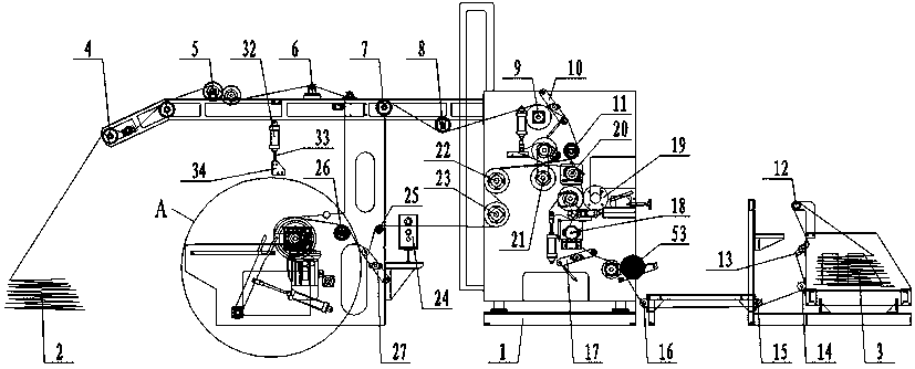
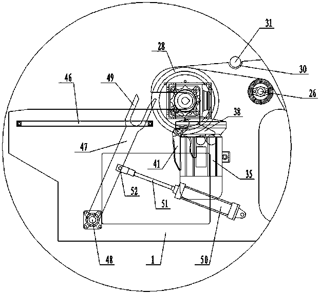
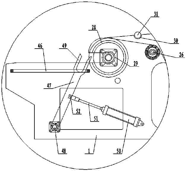
[0014] Such as figure 1 , figure 2 , image 3 , Figure 4 , Figure 5 As shown, the fully automatic hot melt adhesive laminating machine includes: a frame 1, a front discharging device 2 arranged at the front end of the frame 1, and a rear discharging device 3 arranged at the rear end of the frame 1, where the front discharging device 2 The back end of the frame 1 is provided with a cloth spreading rubber roller 4, and the frame 1 at the rear end of the cloth spreading rubber roller 4 is provided with a dividing and flattening roller 5, and the machine at the rear of the dividing and flattening roller 5 A correction device 6 is provided on the frame 1, a first support roller 7 is provided on the frame 1 at the rear end of the correction device 6, and a first opening roller is provided on the frame 1 at the rear end of the first support...


PUM


Abstract

The invention discloses a full-automatic hot melt adhesive composite machine. The full-automatic hot melt adhesive composite machine comprises a machine frame, a front feeding device and a rear feeding device wherein the front feeding device is arranged at the front end of the machine frame, and the rear feeding device is arranged at the rear end of the machine frame; a cloth pulling rubber rolleris arranged on the position, at the rear end of the front feeding device, of the machine frame; a separating spreading roller is arranged on the position, at the rear end of the cloth pulling rubberroller, of the machine frame; a deviation correcting device is arranged on the position, at the rear end of the separating spreading roller, of the machine frame; a first supporting roller is arrangedon the the position, at the rear end of the deviation correcting device, of the machine frame; a first full-width roller is arranged on the position, at the rear end of the first supporting roller, of the machine frame; a cloth feeding rubber roller is arranged on the position, at the rear end of the first full-width roller, of the machine frame; a first tension controller is arranged on the position, at the rear end of the cloth feeding rubber roller, of the machine frame; an aluminum full-width roller is arranged on the position, at the lower end of the first controller, of the machine frame; and a first traction roller, a cloth expander and a second traction roller are arranged on the position, at the front end of the rear feeding device, of the machine frame from top to bottom.

Description

Technical field [0001] The invention relates to a compound machine, in particular to a fully automatic hot melt adhesive compound machine. Background technique [0002] With the rapid development of the clothing industry, hot melt adhesive laminating machines have been put forward higher requirements as the main equipment for fabric production. The existing hot-melt adhesive laminating machine often has the disadvantages of uneven warp and weft, uneven thickness and flanging when laminating. At the same time, the existing hot-melt adhesive laminating machine is relatively cumbersome to operate, and one machine requires more than five people to operate at the same time , Especially the winding part requires manual operation throughout the whole process, the degree of automation is low, the labor intensity of the workers is high, and the work efficiency is low. In addition, the existing hot melt adhesive compound machine can only compound between the fabrics, and the compounding me...

Claims


Application Information

Patent Timeline
Patent Type & Authority Applications(China)
IPC IPC(8): B65H18/16B65H20/02B65H35/04B65H37/04B65H19/30
CPCB65H18/16B65H19/30B65H20/02B65H35/04B65H37/04B65H2701/172
Inventor 郭峰王华陈旭
Owner JIANGSU JINFENG LIGHT IND EQUIP CO LTD
Why Eureka
Try Eureka