Bridge deck wet joint structure adopting T-head steel bars and construction method of bridge deck wet joint structure

A construction method and technology for wet joints, applied in bridges, bridge construction, bridge parts, etc., can solve the problems of large welding workload of wet joints, large current traffic impact, cumbersome construction procedures, etc., to ensure construction quality, The effect of shortening construction time and saving labor costs

Pending Publication Date: 2018-04-20
CHONGQING UNIV
View PDF5 Cites 15 Cited by
  • Summary
  • Abstract
  • Description
  • Claims
  • Application Information

AI Technical Summary

Problems solved by technology

When the number of prefabricated concrete bridge decks or prefabricated concrete girders is large, there are the following problems: (1) the welding workload of wet joint reinforcement is huge, which increases the cost of materials, labor and time; (2) the welding of wet joint reinforcement The welding construction time is long, which has a great impact on the current traffic under the bridge; (3) The welding quality of the reserved steel bars is poor, and when the position of the reserved steel bars on the bridge deck is deviated, the position of the steel bars needs to be corrected before welding, and the construction process is cumbersome

Method used


Image

  • Bridge deck wet joint structure adopting T-head steel bars and construction method of bridge deck wet joint structure
  • Bridge deck wet joint structure adopting T-head steel bars and construction method of bridge deck wet joint structure
  • Bridge deck wet joint structure adopting T-head steel bars and construction method of bridge deck wet joint structure

Examples


Embodiment 1

[0037] This embodiment discloses a steel-concrete composite girder precast concrete bridge deck wet joint structure using T-head steel bars, including a plurality of precast concrete bridge decks 1 erected on steel beams.

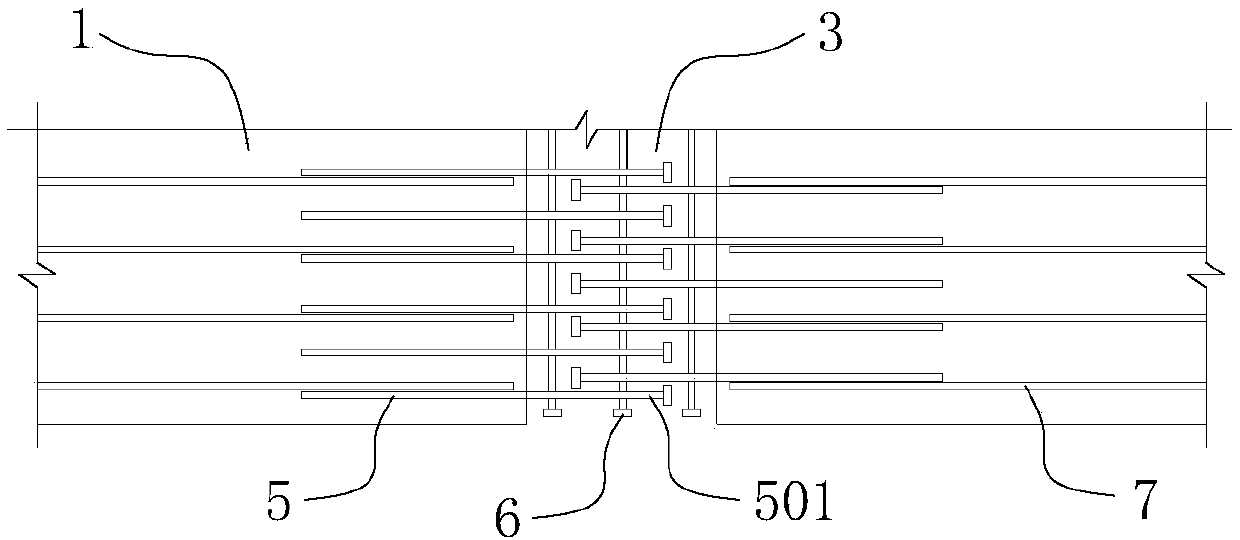
[0038] The prefabricated concrete bridge deck 1 is the roof of the steel-concrete composite beam, which is prefabricated in the prefabrication factory. The prefabricated concrete bridge deck 1 is provided with upper and lower layers of common steel bars 7 for the concrete bridge deck. see figure 1 , wet joints 3 are formed at intervals between two adjacent precast concrete bridge decks 1 .

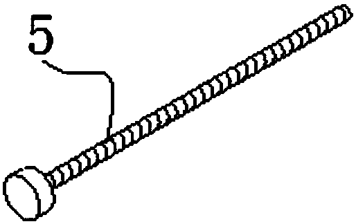
[0039] The upper and lower layers of T-head steel bars 5 are pre-embedded on the side near the wet joint of the precast concrete bridge deck 1 . The pre-embedded part of the T-head steel bar 5 in the bridge deck overlaps with the common steel bar 7 of the concrete bridge deck. The part of the T-head reinforcing bar 5 protruding from the precast concrete bridge deck 1...

Embodiment 2

[0043] This embodiment discloses a bridge deck wet joint structure using T-head steel bars, including a plurality of prefabricated beams 2 arranged along the bridge direction.

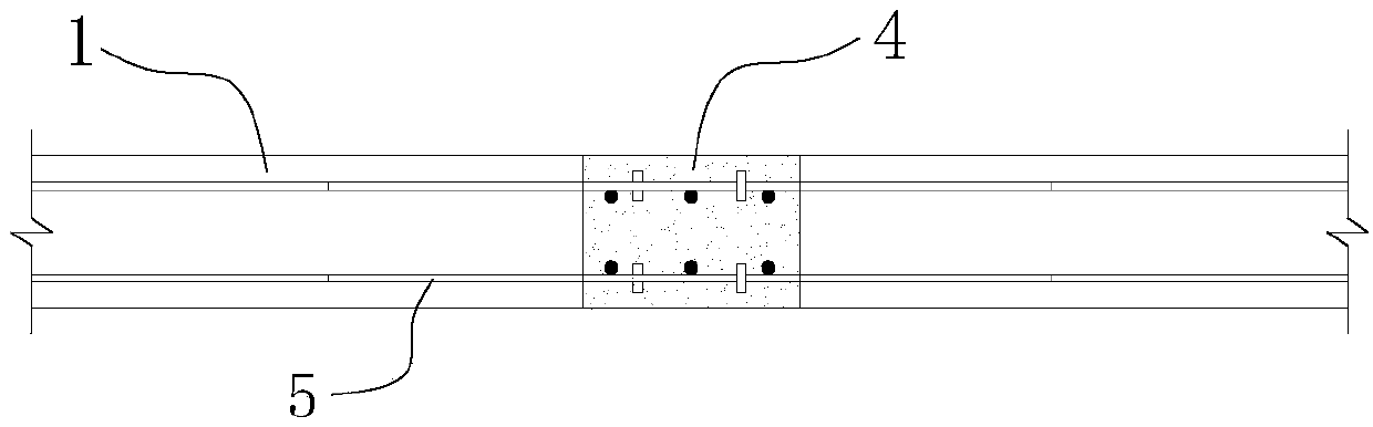
[0044] see image 3 , the prefabricated beam 2 is a precast concrete T-beam. Wet joints 3 along the bridge direction are formed at intervals between two adjacent prefabricated beams 2 . The side near the wet joint of the prefabricated beam 2 is the horizontal section 201 of the prefabricated beam bridge deck. see image 3 T-head reinforcing bars 5 extending to wet joints 3 are arranged in the horizontal section 201 of the prefabricated beam bridge deck. The T-head anchor ends 501 between the adjacent prefabricated beam horizontal sections 201 are arranged in a staggered manner. The projections corresponding to the T-head anchoring end 501 have a length overlap.

[0045] In-situ wet joint concrete 4 is cast in the wet joint 3 . The wet joint concrete 4 is made of high-performance low-shrinkage or mi...

Embodiment 3

[0047] This embodiment discloses a bridge deck wet joint structure using T-head steel bars, including a plurality of prefabricated beams 2 arranged along the bridge direction.

[0048] see Figure 4 , the prefabricated beam 2 is a precast concrete small box girder. Wet joints 3 along the bridge direction are formed at intervals between two adjacent prefabricated beams 2 . The side near the wet joint of the prefabricated beam 2 is the horizontal section 201 of the prefabricated beam bridge deck. T-head reinforcing bars 5 extending to wet joints 3 are arranged in the horizontal section 201 of the prefabricated beam bridge deck. The T-head anchor ends 501 between the adjacent prefabricated beam horizontal sections 201 are arranged in a staggered manner. The projections of the corresponding T-head anchoring ends 501 along the length direction of the wet joint have a length overlap.

[0049] In-situ wet joint concrete 4 is cast in the wet joint 3 . The wet joint concrete 4 is ...


PUM


Abstract

The invention provides a bridge deck wet joint structure adopting T-head steel bars and a construction method of the bridge deck wet joint structure. The bridge deck wet joint structure comprises a plurality of precast concrete bridge decks erected on girders; a plurality of T-head steel bars are pre-buried in the precast concrete bridge decks at the sides close to wet joints; the extending partsof the T-head steel bars are T-head anchoring ends; the T-head anchoring ends between two adjacent precast concrete bridge decks are arranged in a staggered mode; projections of the corresponding T-head anchoring ends have overlapped length; and wet joint concrete is cast in the wet joints in situ, so that two adjacent precast concrete bridge decks can be connected into a whole. The construction method of the bridge deck wet joint structure comprises the steps of pre-burying the T-head steel bars, casting concrete, performing hoisting in place, casting wet joint concrete and the like. The bridge deck wet joint structure simplifies the construction steps, obviously reduces the great welding workload caused by the traditional design, reduces the construction cost, reduces the influence on the existing traffic, improves the construction efficiency, and has wide application prospects.

Description

technical field [0001] The invention relates to the technical field of bridge structures, in particular to a bridge deck wet joint structure. Background technique [0002] In bridge construction, prefabricated steel-concrete composite beams are favored by bridge builders because they can give full play to the mechanical properties of steel and concrete, and are widely used in practical projects; steel-concrete composite bridges are made of steel The beam is combined with the concrete bridge deck. The concrete bridge deck can be prefabricated in blocks in the factory. After hoisting, it is combined with the steel beam through the shear connector at the wet joint position to form a steel-concrete composite beam as a whole. Prefabricated concrete small box girders and T-beams have been widely used in the construction of small and medium-span bridges in my country for a long time. Due to the mature design method and construction technology, the prefabricated concrete girders hav...

Claims


Application Information

Patent Timeline
Patent Type & Authority Applications(China)
IPC IPC(8): E01D19/06
CPCE01D19/067
Inventor 秦凤江尹志伟狄谨宋锦瑞韩斌朋茜
Owner CHONGQING UNIV
Why Eureka
Try Eureka