Novel belt spring support debris flow protective wall and construction method thereof

A debris flow and retaining wall technology, applied in the direction of dams, gravity dams, etc., can solve the problems of disaster loss, increase the flow and destructiveness of debris flow, and fail to achieve the expected prevention and control effect, so as to ensure stability, durability, and good The effect of elastic support capacity

Pending Publication Date: 2018-04-20
ZHEJIANG UNIV
View PDF6 Cites 7 Cited by
  • Summary
  • Abstract
  • Description
  • Claims
  • Application Information

AI Technical Summary

Problems solved by technology

Under complex geological environment conditions, the traditional gravity retaining wall is subjected to special and changeable loads. Once the dam collapses during the debris flow outbreak, not only the expected prevention and control effect cannot be achieved, but the dam body and the solid materials it blocks will also be damaged. It will become the source of loose solid matter for debris flow, directly participate in the movement of debris flow, increase the flow and destructiveness of debris flow, and may even cause more unexpected disaster losses

Method used


Image

  • Novel belt spring support debris flow protective wall and construction method thereof
  • Novel belt spring support debris flow protective wall and construction method thereof
  • Novel belt spring support debris flow protective wall and construction method thereof

Examples


Embodiment Construction

[0023] The present invention will be described in further detail below in conjunction with the accompanying drawings and specific embodiments.

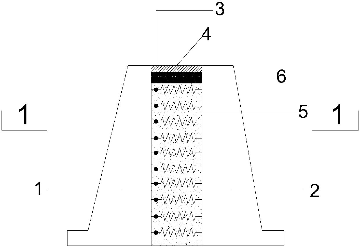
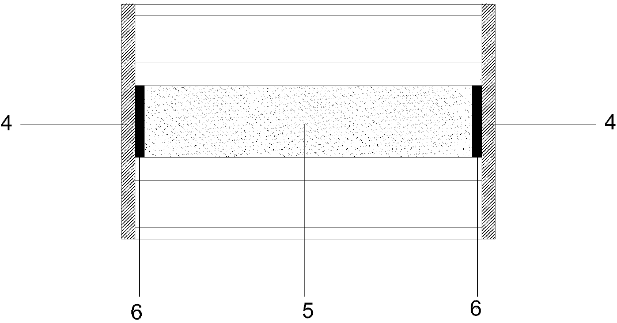
[0024] like figure 1 As shown, a new type of spring-supported debris flow protective retaining wall provided in this embodiment includes a front gravity retaining wall 1, a rear gravity retaining wall 2, a spring support 3 and a waterproof cover 4; the front gravity retaining wall Wall 1 is located at the outermost part of the entire protective retaining wall (the side of the debris flow impact surface), and is made of concrete with a strength grade greater than or equal to C40; the rear gravity retaining wall 2 is located at the innermost side of the entire protective retaining wall, and is made of concrete with a strength greater than or equal to C20 Made of concrete; between the front gravity retaining wall 1 and the rear gravity retaining wall 2, a number of spring supports 3 are layered and fixed; between the front gravity retain...


PUM


Abstract

The invention discloses a novel belt spring support debris flow protective wall and a construction method thereof. The debris flow protective wall comprises a front gravity retaining wall, a rear gravity retaining wall, a belt spring support and waterproof cover plates. The belt spring support comprises an inner pipe structure. The inner pipe structure is composed of first inner pipes and second inner pipes, and the first inner pipes and the second inner pipes are of different sizes and are connected in a staggered and nested mode. The outer side of the inner pipe structure is sleeved with outer casing pipes and springs which are arranged in a staggered mode. The two ends of each spring are fixed to the two adjacent outer casing pipes correspondingly. The space between the front gravity retaining wall and the rear gravity retaining wall is filled with gravel filler. The upper portion and the two sides of the whole protective wall are covered with the waterproof cover plates. Compared with a traditional support, the novel support composed of the inner pipes, the springs and the outer casing pipes can guarantee stability more easily when bearing impact loads. Compared with a traditional gravity retaining wall, the debris flow protective wall of the design can block debris flow more effectively, less power impact is borne by the protective wall through the flexible structure, andreliable stability is achieved.

Description

technical field [0001] The invention relates to the field of mud-rock flow safety protection, in particular to a novel mud-rock flow protective retaining wall with spring support and a construction method thereof. Background technique [0002] The dynamic pressure of mud-rock fluid slurry and the impact force of rocks are typical impact loads, which are characterized by a short action time (mostly measured in milliseconds, microseconds or even nanoseconds), but will generate extremely high pressure, eventually causing the medium Movement, material failure, and failure of entire structures. Under complex geological environment conditions, the traditional gravity retaining wall is subjected to special and changeable loads. Once the dam collapses during the debris flow outbreak, not only the expected prevention and control effect cannot be achieved, but the dam body and the solid materials it blocks will also be damaged. It will become the source of loose solid matter for debr...

Claims


Application Information

Patent Timeline
Patent Type & Authority Applications(China)
IPC IPC(8): E02B7/10
CPCE02B7/10
Inventor 李奖江淇熙钮家军胡钿钿凌道盛
Owner ZHEJIANG UNIV
Why Eureka
Try Eureka