Water draining valve of gas storage barrel

A technology of water discharge valve and air storage tank, which is applied in the field of machinery, can solve the problems of easy jamming, small water output, and low water discharge efficiency, and achieve the effects of improving installation convenience, increasing connection strength, and high overall strength

Pending Publication Date: 2018-04-20
玉环先锋汽车零部件有限公司
View PDF7 Cites 0 Cited by
  • Summary
  • Abstract
  • Description
  • Claims
  • Application Information

AI Technical Summary

Problems solved by technology

[0006] Due to the fact that the drawstring is directly connected to the lower end of the drain valve assembly, the drain valve solves the problem of inconvenient installation. However, the drain valve has the problem of low reliability: the drain valve always discharges water through the drawstring Yes, the pull rope is connected horizontally, and the water discharge valve assembly is vertically installed. When the driver pulls the end of the water discharge valve assembly through the pull rope, the upper end of the water discharge valve assembly can only be tilted at an angle to one side. This results in a small amount of water output and low water discharge efficiency; in addition, because the upper end of the water discharge valve assembly is tilted to one side for water discharge, it is easy to be blocked during the upward reset process by the return spring without effectively closing the

Method used


Image

  • Water draining valve of gas storage barrel
  • Water draining valve of gas storage barrel
  • Water draining valve of gas storage barrel

Examples


Embodiment Construction

[0042] The following are specific embodiments of the present invention and in conjunction with the accompanying drawings, the technical solutions of the present invention are further described, but the present invention is not limited to these embodiments.

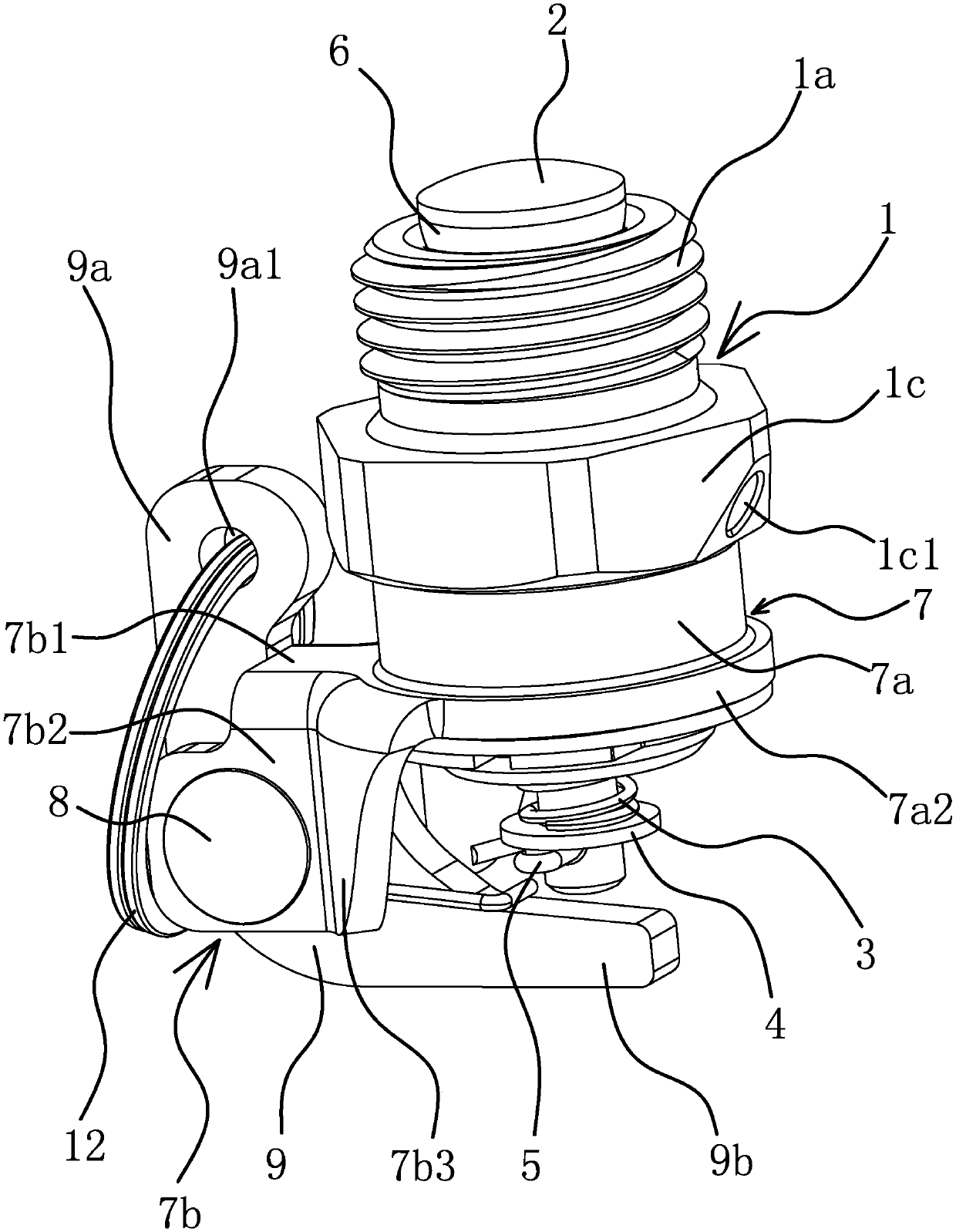
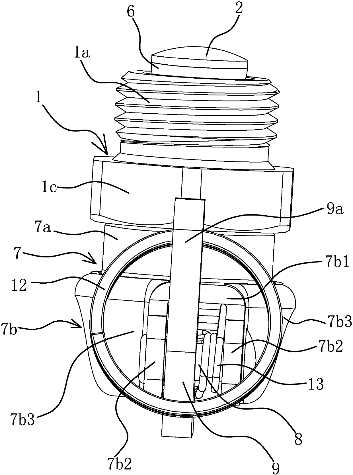
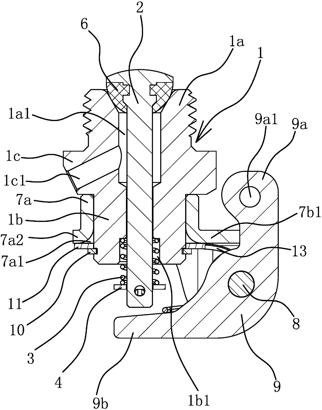
[0043] Such as figure 1 , figure 2 and image 3 As shown, a water release valve for an air storage tank includes a cylindrical valve body 1, the upper end of the valve body 1 is the installation end 1a, the lower end of the valve body 1 is the positioning end 1b, and the outer peripheral side of the middle part of the valve body 1 is provided with a protruding connection Part 1c, the connection part 1c is hexagonal. A water discharge channel 1a1 is arranged in the axial direction in the installation end 1a, the upper port of the water discharge channel 1a1 is located on the end face of the installation end 1a, the positioning end 1b of the valve body 1 is provided with an installation cavity 1b1, and the lower port of t...


PUM


Abstract

The invention provides a water draining valve of a gas storage barrel, belongs to the technical field of machinery, and solves the problem that an existing water draining valve is inconvenient to mount and irregular to use. The water draining valve of the gas storage barrel comprises a valve body, the upper end of the valve body is a mounting end, a control rod which can axially move along the valve body and can control opening and closing of the valve body penetrates in the valve body, the lower end of the control rod extends out of the lower end of the valve body, the lower end of the valvebody is a positioning end, a rotary barrel which can rotate is arranged on the outside of the positioning end in a sleeving manner, the rotary barrel comprises a barrel body and a mounting seat, the barrel body is cylindrical and is axially limited on the positioning end, the mounting seat and the barrel body are connected integrally, the mounting seat is positioned on a peripheral side of the barrel body and is hinged to an oscillating bar, one end of the oscillating bar is a connecting end which is connected with a pull rope, the other end of the oscillating bar is a pushing end, the pushingend is positioned below the lower end of the control rod, and when the connecting end of the oscillating bar is pulled, the pushing end can upwards push the control rod to open the valve. The water draining valve of the gas storage barrel has the advantages of convenience in mounting, high use reliability and the like.

Description

technical field [0001] The invention belongs to the technical field of machinery, and relates to a water discharge valve, in particular to a water discharge valve of an air storage tank. Background technique [0002] The air storage tank is a gas storage device in the automobile braking system, which is used to store the air compressed by the air compressor for automobile braking or other gas. The air compressed by the air compressor will contain a large amount of oil, water and other media. In order to ensure the reliability of the braking system, the driver must discharge it regularly, especially for the air storage tank. If there is too much water in the air storage tank, Once the weather becomes cold, it is easy to cause the accumulated water in the air storage tank to freeze and affect the normal air supply. For this reason, people have designed the drain valve that is used for draining to be installed in the bottom of air storage tank, so that the driver can regularly...

Claims


Application Information

Patent Timeline
Patent Type & Authority Applications(China)
IPC IPC(8): F16K31/44B60T17/04
CPCF16K31/44B60T17/043
Inventor 林华忠叶开锋
Owner 玉环先锋汽车零部件有限公司
Why Eureka
Try Eureka