Non-contact type valve position indicating mechanism

An indicating mechanism, non-contact technology, applied in valve devices, mechanical equipment, engine components, etc., can solve problems such as reliability reduction, and achieve the effects of high reliability, simple structure, and improved service life

Inactive Publication Date: 2018-04-20
SUFA TECH IND CNNC
View PDF4 Cites 1 Cited by
  • Summary
  • Abstract
  • Description
  • Claims
  • Application Information

AI Technical Summary

Problems solved by technology

This type of valve is generally installed in a harsh environment with high humidity, high temperature, and radiation, which puts forward higher requirements for the position indicating mechanism, and the reliability of the traditional mechanical position indicating structure is greatly reduced.

Method used


Image

  • Non-contact type valve position indicating mechanism
  • Non-contact type valve position indicating mechanism
  • Non-contact type valve position indicating mechanism

Examples


Embodiment Construction

[0011] The present invention is described in detail below in conjunction with accompanying drawing and example:

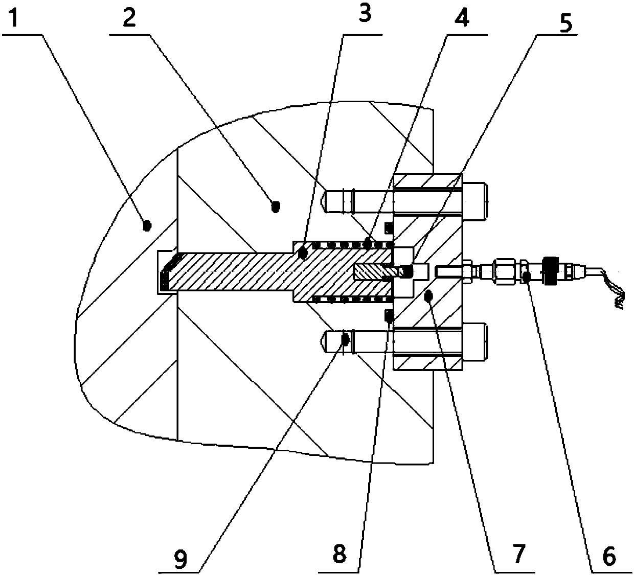
[0012] Such as figure 1 As shown, a non-contact valve position indicating mechanism, which includes a pin 3, a spring 4, a magnet 5, a magnetic induction switch 6, a cover 7, a seal 8 and a screw 9. The entire position indicating structure is installed on the side wall of the pressure bearing part 2 of the valve, and a hole is opened on the side wall of the pressure bearing part 2 of the valve for installing the latch 3 . The head of the pin 3 is designed as an inclined plane, so that when the valve stem 1 moves downward, the pin 3 can be pushed to move laterally. At the same time, the head of the pin 3 is surfacing with hard alloy to improve wear resistance, and the tail of the pin 3 is installed with A spring 4 is installed between the second half of the latch 3 and the cover 7 to provide resilience when the latch 3 reciprocates. A seal 8 is arranged between th...


PUM


Abstract

The invention belongs to a valve position indicating mechanism, and particularly relates to a novel non-contact type valve position indicating mechanism. The indicating mechanism comprises a bolt, a spring, a magnet, a magnetic induction switch, a sealing cover, a sealing part and screws; the sealing cover is fixed on the side wall of a valve pressure bearing piece through the screws; the bolt isarranged on the side, facing the valve pressure bearing piece, of the sealing cover, the spring sleeves the bolt, and a slope is arranged at the front end of the bolt; a groove is formed in the side wall of a valve rod, and the shape of the groove is matched with the most front end of the bolt; the magnet is arranged at the most rear end of the bolt; and the magnetic induction switch is arranged on the side, backing onto the valve pressure bearing piece, of the sealing cover, and the position of the magnetic induction switch is matched with the position of the magnet. The valve position indicating mechanism has the advantages that the induction is sensitive, the reliability is high, structure is simple, and no extra mounting space is occupied.

Description

technical field [0001] The invention belongs to a valve position indicating mechanism, in particular to a novel non-contact valve position indicating mechanism. Background technique [0002] Valves are mechanical devices that control fluids, and are the basic components in pipelines. They are widely used in petrochemical, natural gas, nuclear power and thermal power industries. The position indication of the valve is an important part of the valve, which is used to indicate the opening and closing status or opening information of the valve. The requirements of the valve position indication mechanism are sensitive indication, long service life and high reliability. [0003] For the nuclear power thermal power industry, especially in nuclear power plants, many valves are installed in the safety system. These valves are closed under normal working conditions, and are required to be opened under accidental working conditions to connect the safety system. This type of valve is g...

Claims


Application Information

Patent Timeline
Patent Type & Authority Applications(China)
IPC IPC(8): F16K37/00
CPCF16K37/0083
Inventor 吴辉倪项斌王志敏李军业陈时健王锐
Owner SUFA TECH IND CNNC
Why Eureka
Try Eureka