Height and steering accurately-adjustable display
A precise adjustment and display technology, applied in the direction of instruments, supporting machines, friction transmission devices, etc., can solve the problems of difficult to accurately adjust the height and steering of the liquid crystal display, and achieve the effect of improving the user experience, high adjustment accuracy, and ensuring accuracy.
- Summary
- Abstract
- Description
- Claims
- Application Information
AI Technical Summary
Problems solved by technology
Method used
Image
Examples
Embodiment 1
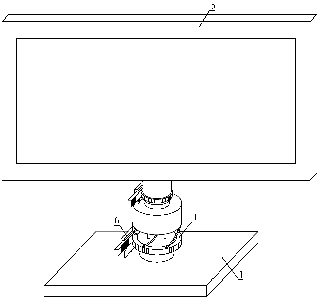
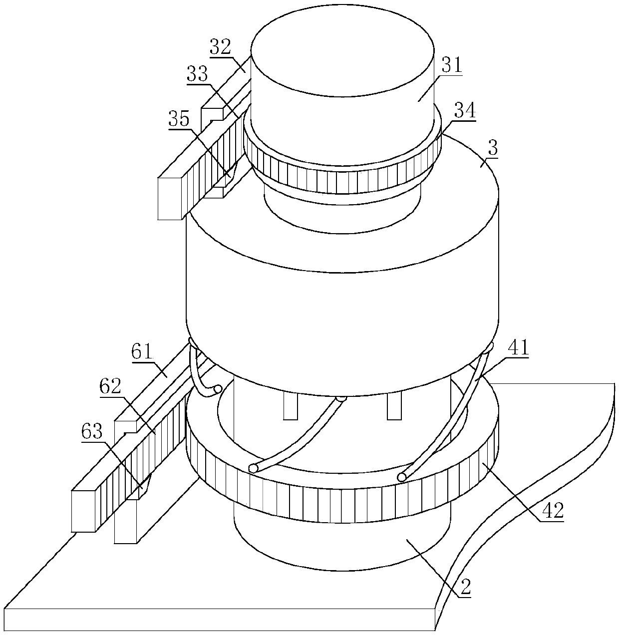
[0023] Such as figure 1 and figure 2 As shown, the present invention includes a base 1, the base 1 is connected with a fixed rod 2, the fixed rod 2 is sleeved with a sleeve 3, and the fixed rod 2 is provided with a push-pull mechanism 4 for driving the sleeve 3 to move; The other end is connected with rotating seat 31 by thrust bearing, and the other end of rotating seat 31 is fixed with display screen main body 5, is fixed with rotating chute 32 on the sleeve 3, is provided with rotating rack 33 in rotating chute 32 inner sleeves, and rotates Seat 31 is fixed with rotating ring gear 34, and rotating rack 33 is meshed with rotating ring gear 34, and is engaged with the rotating wedge block 35 that prevents rotating rack 33 from moving voluntarily between rotating rack 33 and rotating chute 32.
[0024] The base 1 of the present invention is connected with a fixed rod 2. When the push-pull mechanism 4 on the fixed rod 2 is driven, the push-pull mechanism 4 can push up or pull...
Embodiment 2
[0026] On the basis of Embodiment 1, the push-pull mechanism 4 includes a push-pull rod 41, one end of the push-pull rod 41 is hinged with the sleeve 3, and the other end of the push-pull rod 41 is hinged with a rotating ring 42, and the rotating ring 42 is connected to the fixed rod through a bearing 2, the base 1 is equipped with an engagement mechanism 6 for changing the direction of the rotating ring 42; a limit bar is arranged on the fixed rod 2, and a limit groove is arranged on the inner wall of the sleeve 3, and the limit bar is sleeved in the limit groove.
[0027] After turning the rotating circle 42 to a certain position, fix its position with the engagement mechanism 6, then the direction in which the push-pull rod 41 tilts is determined, and the projected length of the push-pull rod 41 in the vertical direction is determined, and the sleeve 3 and the display screen main body 5 The lifting height is determined. Therefore, it is only necessary to adjust the rotating...
Embodiment 3
[0029] On the basis of Embodiment 1 or Embodiment 2, the engaging mechanism 6 includes a chute 61 , a rack 62 is sleeved in the chute 61 , and a ring gear is arranged on the rotating ring 42 , and the ring gear meshes with the rack 62 .
[0030] When the rack 62 is pulled, the rack 62 slides in the chute 61 , the rack 62 meshes with the ring gear, and the rack 62 pulls the rotating ring 42 to rotate accordingly. Therefore, only the rack 62 needs to be pulled, and the turning direction of the rotating ring 42 can be precisely adjusted, and the height of the display screen main body 5 can be precisely adjusted, which improves the convenience of operation.
PUM
 Abstract
Description
Claims
Application Information
 - R&D
- Intellectual Property
- Life Sciences
- Materials
- Tech Scout
- Unparalleled Data Quality
- Higher Quality Content
- 60% Fewer Hallucinations
Browse by: Latest US Patents, China's latest patents, Technical Efficacy Thesaurus, Application Domain, Technology Topic, Popular Technical Reports.
© 2025 PatSnap. All rights reserved.Legal|Privacy policy|Modern Slavery Act Transparency Statement|Sitemap|About US| Contact US: help@patsnap.com


