Air flue assembly
A technology of air duct components and air duct plates, which is applied in the direction of pipeline layout, space heating and ventilation details, household heating, etc., can solve the problems of high mold cost, low molding efficiency of air duct components, and extremely high mold requirements, and achieve Improve production efficiency, simplify the installation structure, and reduce the effect of the structure
- Summary
- Abstract
- Description
- Claims
- Application Information
AI Technical Summary
Problems solved by technology
Method used
Image

Examples
Embodiment Construction
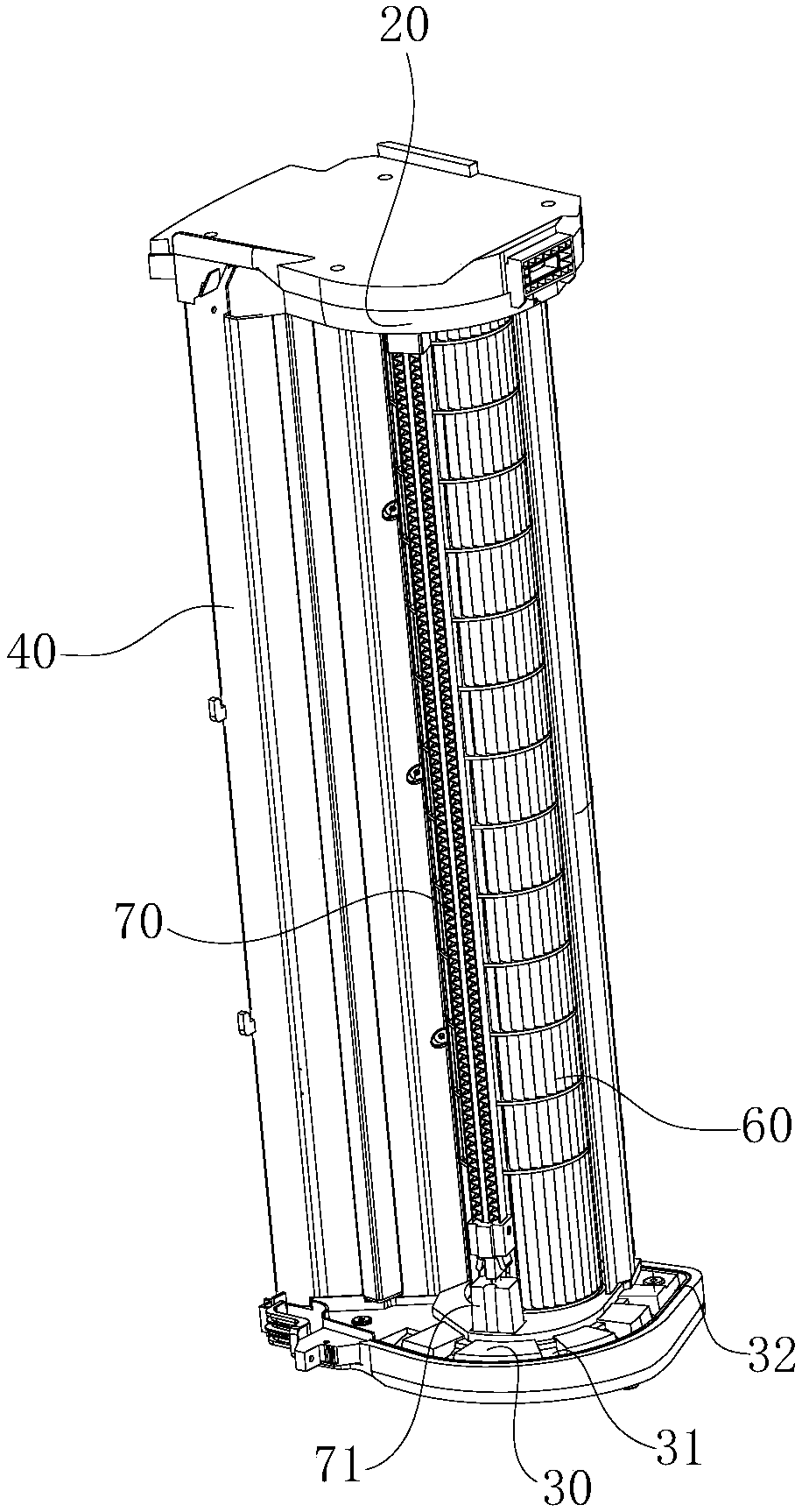
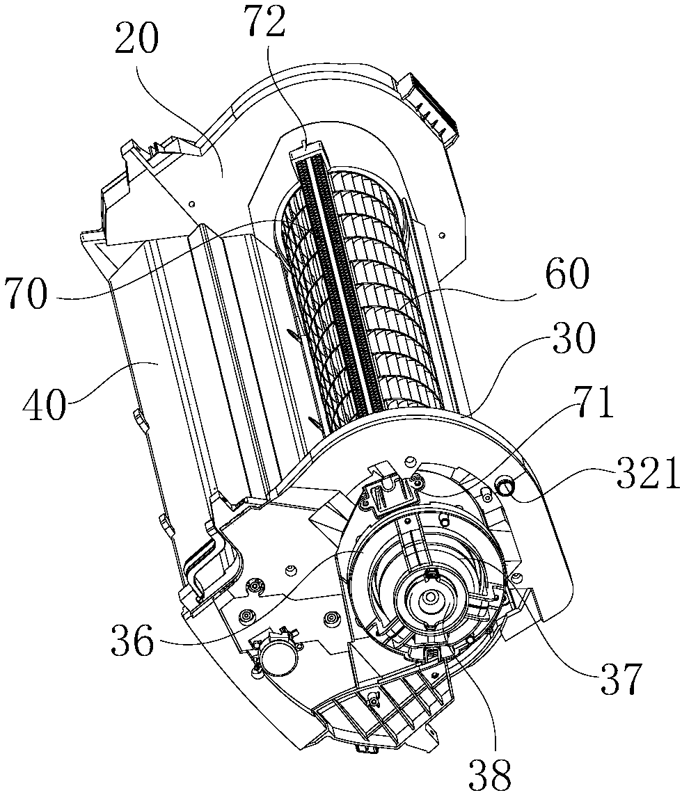
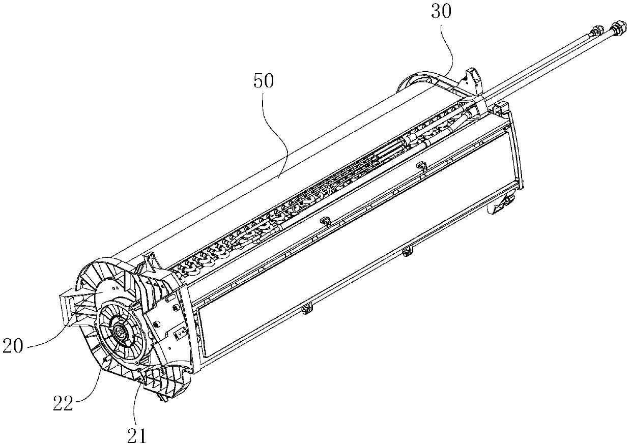
[0023] refer to Figure 1 to Figure 9 , the characteristics of the air duct components are described in detail as follows:
[0024] The air duct assembly includes a first air duct plate 10, first and second end plates 20, 30 are provided at both ends of the first air duct plate 10, and one end of the first air duct plate 10 is connected to the first end plate 20 is fixedly connected as one, and the other end of the first air channel plate 10 forms a detachable connection with the second end plate 30, and a second The air channel plate 40, the second air channel plate 40 and the first air channel plate 10 are spaced apart, and the second air channel plate 40 and the first air channel plate 10 form a space for accommodating the swinging wind assembly. The air outlet opening, a heat exchanger 50 is also provided between the first and second end plates 20, 30, the cross section of the heat exchanger 50 is V-shaped, and the opening of the heat exchanger 50 A cross-flow fan 60 is ...
PUM
 Abstract
Description
Claims
Application Information
 - Generate Ideas
- Intellectual Property
- Life Sciences
- Materials
- Tech Scout
- Unparalleled Data Quality
- Higher Quality Content
- 60% Fewer Hallucinations
Browse by: Latest US Patents, China's latest patents, Technical Efficacy Thesaurus, Application Domain, Technology Topic, Popular Technical Reports.
© 2025 PatSnap. All rights reserved.Legal|Privacy policy|Modern Slavery Act Transparency Statement|Sitemap|About US| Contact US: help@patsnap.com