Heat pipe sealing structure

A sealing structure and heat pipe technology, which is applied in indirect heat exchangers, lighting and heating equipment, etc., can solve the problems of leakage of the sealing structure at the partition plate of the heat pipe heat exchanger, and achieve low processing cost, simple and convenient disassembly and replacement, and simple installation convenient effect

Pending Publication Date: 2018-04-20
NANJING SHENGNUO HEAT PIPE
View PDF0 Cites 3 Cited by
  • Summary
  • Abstract
  • Description
  • Claims
  • Application Information

AI Technical Summary

Problems solved by technology

[0014] The invention provides a new heat pipe sealing structure to solve the problem of leakage of the sealing structure at the partition plate

Method used


Image

  • Heat pipe sealing structure
  • Heat pipe sealing structure

Examples


Embodiment Construction

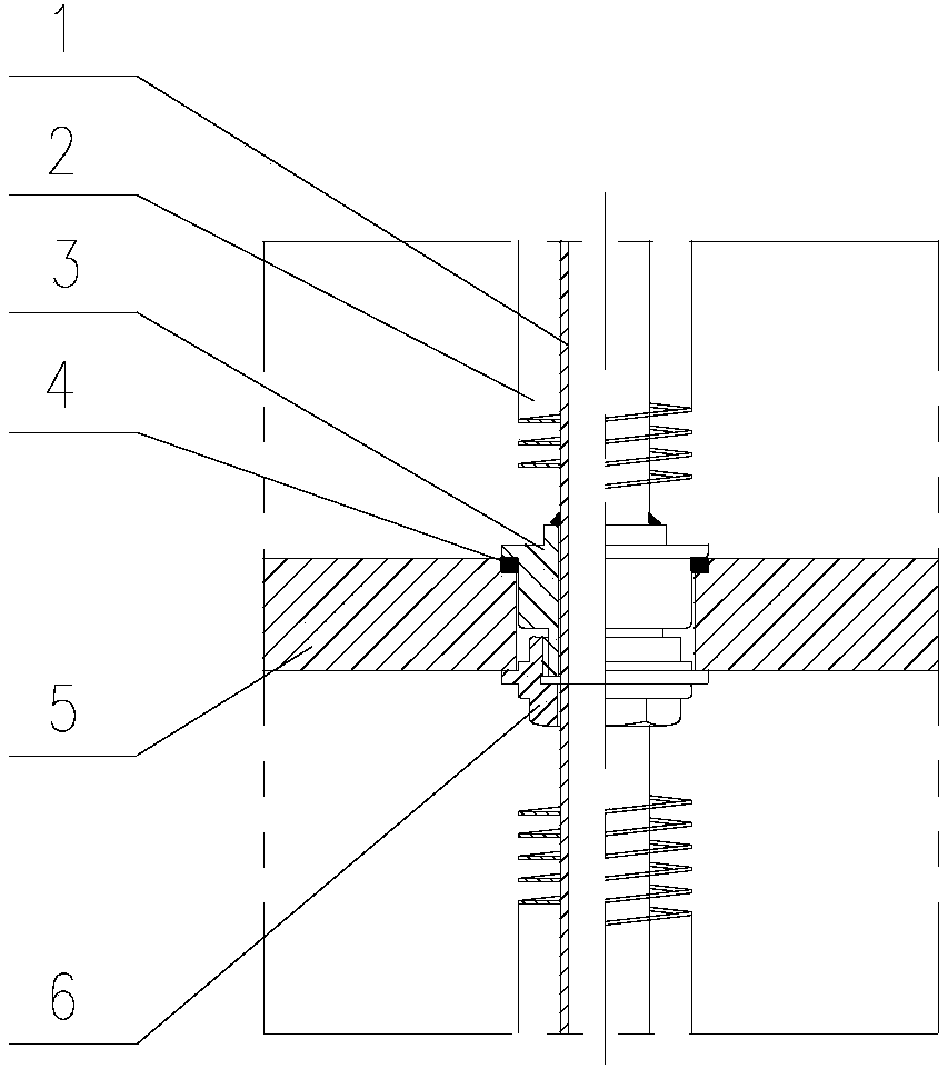
[0024] like figure 2 As shown, the heat pipe sealing structure of the present invention includes a partition 5 , a sealing block 3 , a sealing ring 4 , and a compression nut 6 .

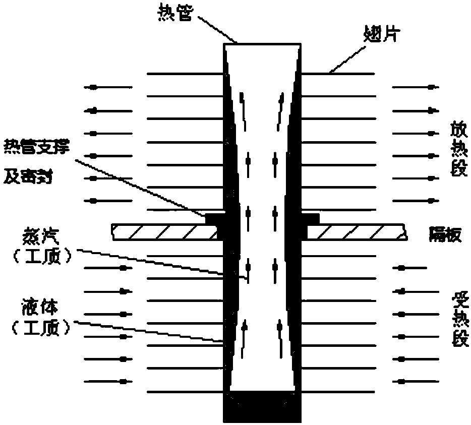
[0025] The heat pipe 1 can be a light pipe, a finned pipe and other structures;

[0026] The sealing surface of the gasket on the partition is set above the hole of the partition and sinks into the partition, which is convenient for the sealing ring 4 to limit and protect the sealing surface;

[0027] The sealing block 3 is welded with the heat pipe 1, and is installed from the top to the partition hole along with the heat pipe 1. The upper part is provided with a sealing surface to compress the sealing ring 4, and the lower part is provided with an external thread to cooperate with the internal thread of the compression nut 6;

[0028] The compression nut 6 is installed below the partition hole, and the purpose of compressing the sealing ring is achieved by rotating the compression nut 6 .

[002...


PUM


Abstract

The invention provides a heat pipe sealing structure, which includes a partition and a sealing block. The partition is provided with a partition hole, the heat pipe passes through the partition hole, the partition isolates the cold flow section and the hot flow section of the heat pipe, and the sealing block is welded on the heat pipe. And pass through the partition hole together with the heat pipe. The upper part of the sealing block is provided with a sealing plate, and the lower part is provided with an external thread section. The external thread section is screwed with a compression nut. By rotating the compression nut, the sealing plate of the sealing block and the partition The upper surface is tightly pressed. The invention has the advantages of simple structure, convenient processing and good sealing performance.

Description

technical field [0001] The invention belongs to the field of heat pipe heat exchangers, in particular to a sealing structure for a partition between a cold-side medium and a hot-side medium of a heat pipe heat exchanger. Background technique [0002] The heat pipe is a heat transfer element with high heat transfer performance. It transfers heat through the phase change latent heat of the working medium in the closed vacuum tube shell. It has the characteristics of large heat transfer capacity and high heat transfer efficiency. [0003] Typical gravity heat pipes such as figure 1 shown. Heat pipe heat exchangers are generally composed of multiple heat pipes, which have many advantages such as high heat transfer efficiency, small resistance loss, compact structure, reliable operation and low maintenance costs. They are widely used in space technology, electronics, metallurgy, power, petroleum, chemical industry, etc. Various industries have been widely used. [0004] The he...

Claims


Application Information

Patent Timeline
IPC IPC(8): F28D15/02
CPCF28D15/0283
Inventor 杜秀萍王明军陈林倪俊陆桂清
Owner NANJING SHENGNUO HEAT PIPE
Why Eureka
Try Eureka